Triaxial force sensor

a technology of force sensor and triaxial force, which is applied in the direction of force measurement, force/torque/work measurement apparatus, instruments, etc., can solve the problems of increasing manufacturing cost and achieve the effect of increasing manufacturing cos

Active Publication Date: 2022-07-21
HONDA MOTOR CO LTD +1
View PDF46 Cites 3 Cited by
  • Summary
  • Abstract
  • Description
  • Claims
  • Application Information

AI Technical Summary

Benefits of technology

[0004]According to the conventional tactile sensor described above, in order to detect forces in orthogonal triaxial directions, it is necessary to planarly arrange a large number of stress detection elements each composed of a single pressing force detection element and four shearing force detection elements. As a result, the sensor is increased in size, and a large number of electrodes are required, so that the number of components is increased, leading to an increase in manufacturing cost.

Problems solved by technology

As a result, the sensor is increased in size, and a large number of electrodes are required, so that the number of components is increased, leading to an increase in manufacturing cost.

Method used


Image

  • Triaxial force sensor
  • Triaxial force sensor
  • Triaxial force sensor

Examples


first embodiment

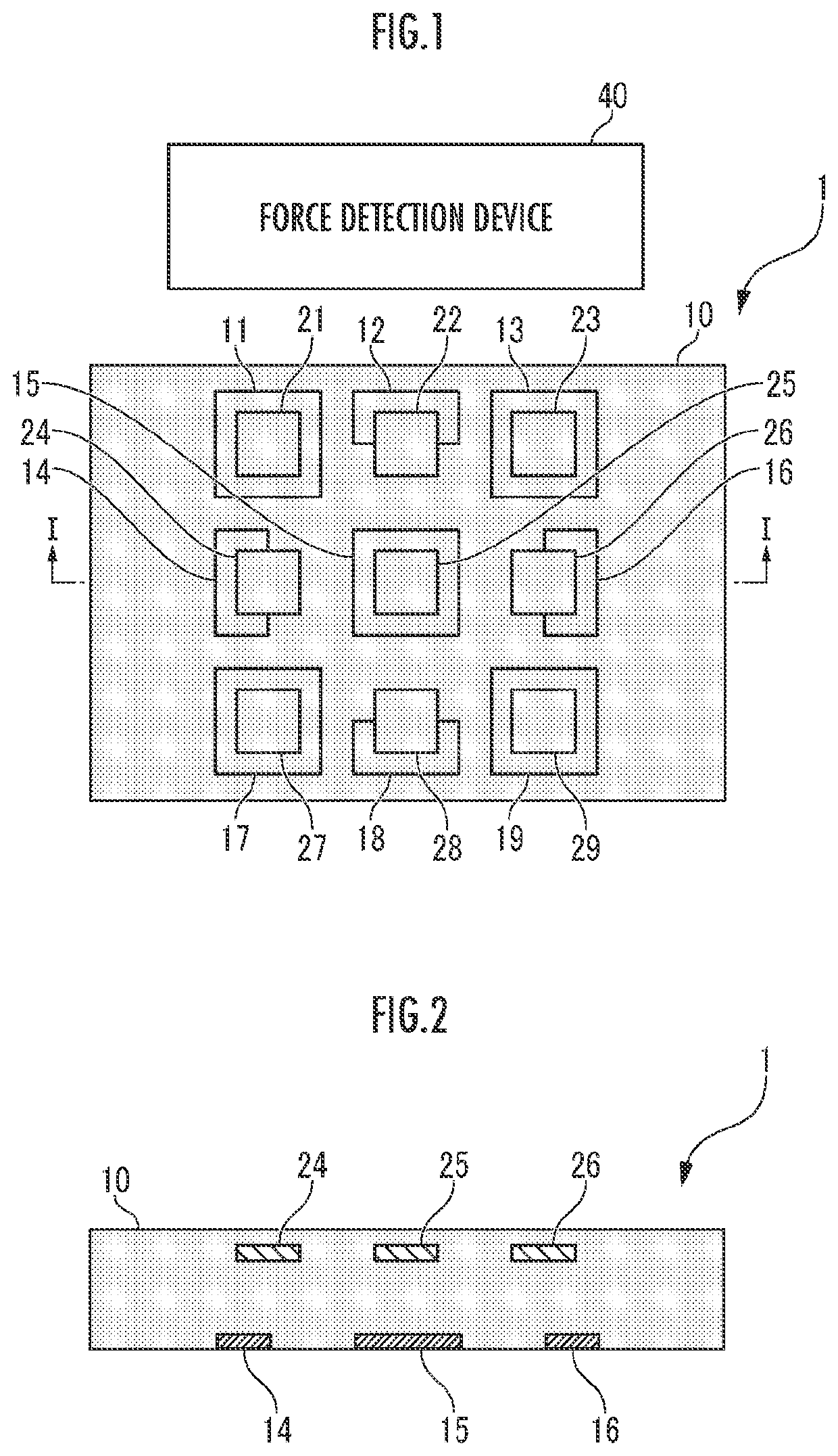
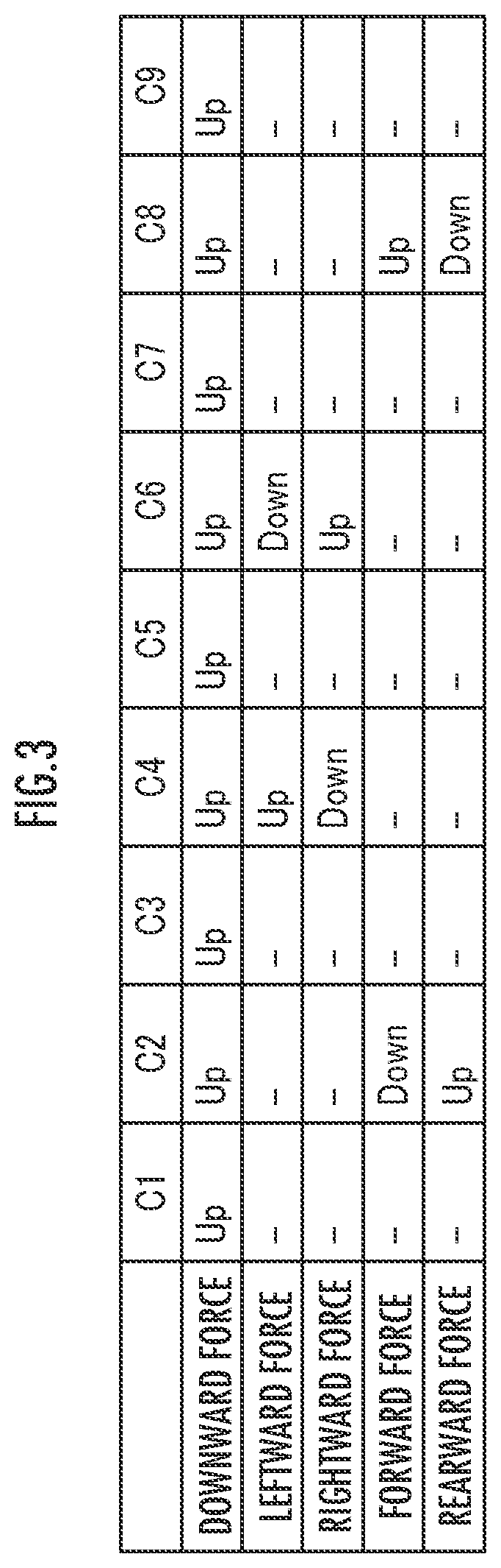
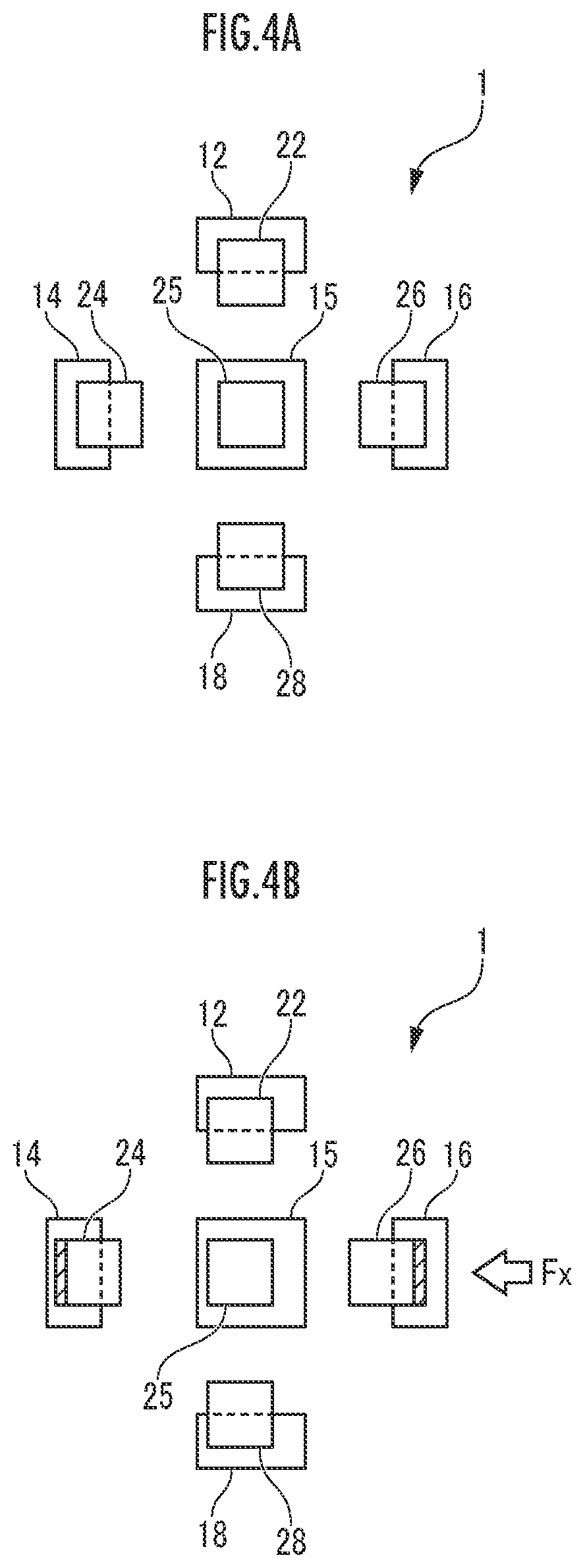
[0034]Hereinafter, a triaxial force sensor according to the present invention will be described with reference to the drawings. The triaxial force sensor 1 shown in FIG. 1 according to the present embodiment is connected to a force detection device 40 via an electric wire (not shown). As will be described later, the force detection device 40 detects the forces in orthogonal triaxial directions acting on the triaxial force sensor 1 on the basis of the detection results of capacitances C1 to C9 by the triaxial force sensor 1.

[0035]As shown in FIGS. 1 and 2, the triaxial force sensor 1 according to the present embodiment includes an electrode support 10, nine first electrodes 11 to 19, and nine second electrodes 21 to 29.

[0036]Note that, in the following description, for convenience, the left side of FIG. 1 is referred to as “left”, the right side of FIG. 1 is referred to as “right”, the lower side of FIG. 1 is referred to as “front”, the upper side of FIG. 1 is referred to as “rear”, ...

second embodiment

[0085]As described above, the triaxial force sensor 100 is configured by the twelve first electrodes 111 to 122 being attached to the electrode support 10 in an orientation parallel to the upper surface of the electrode support 10, and the nine second electrodes 201 to 209 being attached to the electrode support 10 in spaced face-to-face relation to the twelve first electrodes 111 to 122. Furthermore, the single second electrode 201 is disposed in such a manner that the halves of the four first electrodes 111 to 114 overlap the second electrode 201 in plan view.

[0086]Therefore, when a downward force acts on the electrode support 10, the distances between the nine second electrodes 201 to 209 and the twelve first electrodes 111 to 122 change, and on the basis of the resulting changes in capacitance, the downward force acting on the electrode support 10 can be detected at a total of twelve locations. That is, even when a distributed load acts on the electrode support 10, the distribu...


PUM

PropertyMeasurementUnit
capacitanceaaaaaaaaaa
dielectric propertiesaaaaaaaaaa
elasticityaaaaaaaaaa

Abstract

A triaxial force sensor 1 includes nine first electrodes 11 to 19, and nine second electrodes 21 to 29 attached to an electrode support 10 in such a manner that the electrode support 10 is interposed between the nine first electrodes 11 to 19 and the nine second electrodes 21 to 29. A pair of first electrodes 14 and 16 are arranged such that a straight line connecting the two is orthogonal to a straight line connecting a pair of first electrodes 12 and 18, and the second electrodes 22, 24, 26, and 28 are arranged such that the respective halves overlap the first electrodes 12, 14, 16, and 18 in plan view. The sensor has a number of components and size, thereby allowing a reduction in manufacturing cost, in the case of detecting forces in orthogonal triaxial directions.

Description

BACKGROUNDTechnical Field[0001]The present invention relates to a triaxial force sensor.Related Art[0002]Conventionally, a triaxial force sensor described in JP 2014-55985 A is known. The triaxial force sensor is configured to detect forces in orthogonal triaxial directions including distributed loads, and is equipped with a large number of planarly arranged stress detection elements. Each of the stress detection elements is of the piezoelectric element type, and is equipped with a pressing force detection element, one pair of shearing force detection elements, and the other pair of shearing force detection elements. The pair of shearing force detection elements and the other pair of shearing force detection elements are arranged in the shape of a cross in plan view so that the pressing force detection element is located at the center of the cross. The pressing force detection element and the shearing force detection elements are composed of a pair of upper and lower electrodes or t...

Claims


Application Information

Patent Timeline
Patent Type & Authority Applications(United States)
IPC IPC(8): G01L5/165G01L1/14
CPCG01L5/165G01L1/14
Inventor ISHIZAKI, RYUSUKESARWAR, MIRZA SAQUIBMADDEN, JOHN D.W.
Owner HONDA MOTOR CO LTD
Why Eureka
Try Eureka