Fuel cell system

a fuel cell and system technology, applied in fuel cells, transportation hydrogen technology, climate sustainability, etc., can solve the problem of decreasing rigidity of the upper wall portion, and achieve the effect of suppressing the decrease in rigidity of the stack cas

Pending Publication Date: 2022-07-21
HONDA MOTOR CO LTD
View PDF0 Cites 0 Cited by
  • Summary
  • Abstract
  • Description
  • Claims
  • Application Information

AI Technical Summary

Benefits of technology

The present invention solves the problem of misalignment between power lead-out members and through-holes in electronic devices. By making the second through-hole elongated in the stacking direction and compensating for misalignment, the second power lead-out member can be reliably inserted into the second through-hole, even if the position of the second terminal member with respect to the first terminal member in the stacking direction varies. This also prevents a decrease in rigidity of the stack case.

Problems solved by technology

If the length of each of the first through-hole and the second through-hole in the stacking direction is set to be large in advance, there is a problem in that the rigidity of the upper wall portion decreases.

Method used


Image

  • Fuel cell system
  • Fuel cell system
  • Fuel cell system

Examples


Embodiment Construction

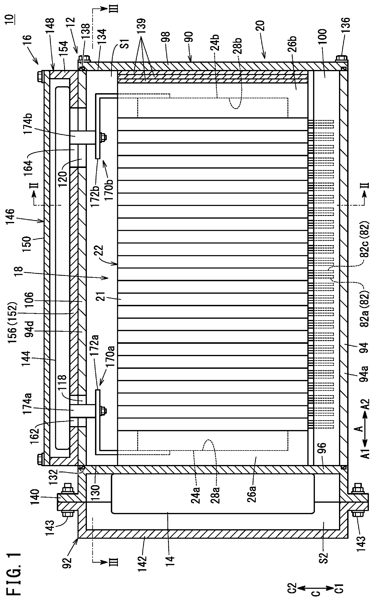
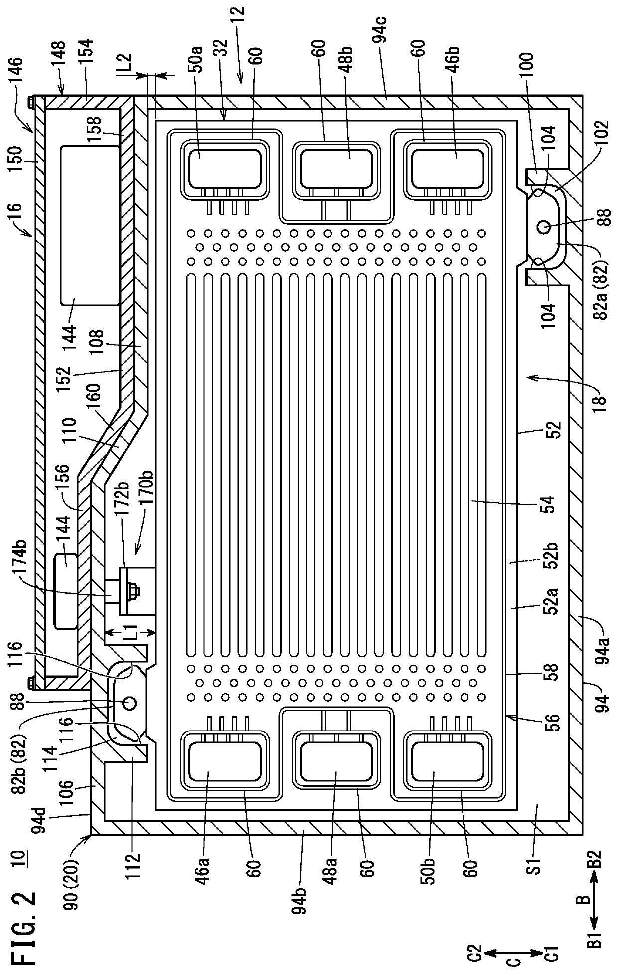
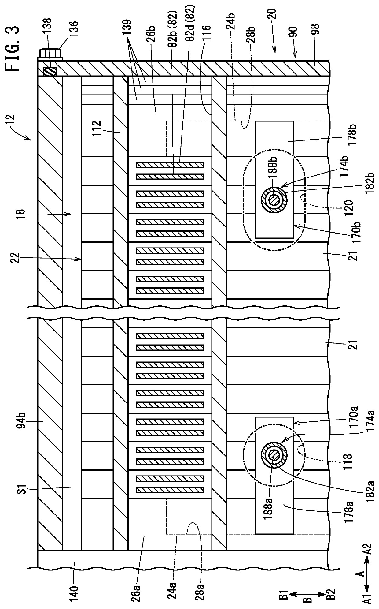
[0022]A fuel cell system 10 shown in FIG. 1 is to be mounted on, for example, a fuel cell electric vehicle (fuel cell vehicle) (not shown). In FIGS. 1 to 3, the fuel cell system 10 includes a fuel cell stack 12, a fuel cell auxiliary device 14, and an electrical unit 16.

[0023]The fuel cell stack 12 includes a stacked member 18 and a case unit 20 that houses the stacked member 18. The stacked member 18 includes a cell stack body 22 in which a plurality of power generation cells 21 are stacked. The fuel cell stack 12 is disposed such that the stacking direction (direction of the arrow A) of the plurality of power generation cells 21 extends horizontally. In the following description, the stacking direction of the plurality of power generation cells 21 may be simply referred to as a “stacking direction”.

[0024]In FIG. 1, a first terminal member 24a and a first insulating plate 26a are disposed outward (in the direction of the arrow A1) in this order at one end (an end in the direction o...


PUM

PropertyMeasurementUnit
lengthaaaaaaaaaa
shapeaaaaaaaaaa
poweraaaaaaaaaa

Abstract

A first through-hole through which a first power lead-out member is inserted and a second through-hole through which a second power lead-out member is inserted are formed in an upper wall portion of a stack case of a fuel cell system. The length of the second through-hole in the stacking direction of the power generation cells is greater than the length of the first through-hole in the stacking direction.

Description

CROSS-REFERENCE TO RELATED APPLICATIONS[0001]This application is based upon and claims the benefit of priority from Japanese Patent Application No. 2021-008044 filed on Jan. 21, 2021, the contents of which are incorporated herein by reference.BACKGROUND OF THE INVENTIONField of the Invention[0002]The present invention relates to a fuel cell system.Description of the Related Art[0003]The fuel cell system includes a stacked member and a stack case that houses the stacked member. The stacked member includes a cell stack body, a first terminal member, and a second terminal member. The cell stack body is formed by stacking a plurality of power generation cells one another. The first terminal member and the second terminal member are provided respectively at both ends of the cell stack body in the stacking direction of the plurality of power generation cells.[0004]The first terminal member is electrically connected to an electrical unit provided at an upper portion of the stack case via t...

Claims


Application Information

Patent Timeline
Patent Type & Authority Applications(United States)
IPC IPC(8): H01M8/2475
CPCH01M8/2475H01M2250/20H01M8/02H01M8/2465Y02T90/40
Inventor NAITO, HIDEHARU
Owner HONDA MOTOR CO LTD
Why Eureka
Try Eureka