Tyre-removal apparatus

Pending Publication Date: 2022-07-28
SNAP ON EQUIP
View PDF0 Cites 0 Cited by
  • Summary
  • Abstract
  • Description
  • Claims
  • Application Information

AI Technical Summary

Problems solved by technology

As mentioned, if this not performed properly, both the bead breaking process and the subsequent tyre removal process may not be effec

Method used


Image

  • Tyre-removal apparatus
  • Tyre-removal apparatus
  • Tyre-removal apparatus

Examples


Embodiment Construction

[0113]In the description which follows, any expressions used, such as “right-hand”, “left-hand”, “above”, “below”, “upper”, “lower”, “horizontal”, “vertical” and the like, are used merely for illustrative purposes and refer to the particular arrangement of the elements present in the attached figures and therefore are not limiting in any way.

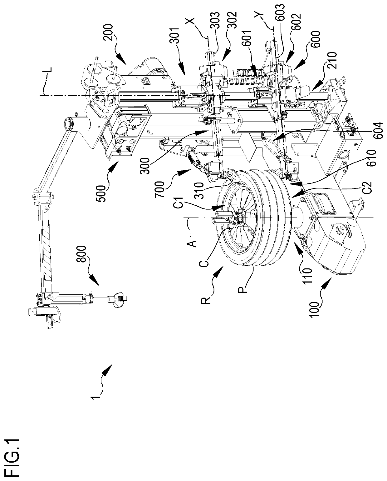
[0114]With reference to the attached figures, 1 denotes overall an apparatus for maintaining vehicle wheels, in particular a tyre-removal apparatus or machine.

[0115]The tyre-removal apparatus 1 comprises a base 100 on which there is mounted a rotating wheel support assembly, referred to in short as “support 110”, preferably of the plate type, on which a wheel R comprising a rim C and a tyre P is reversibly clamped using suitable clamping means known per se.

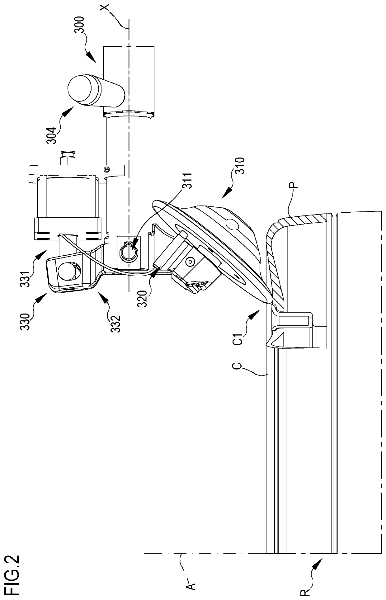
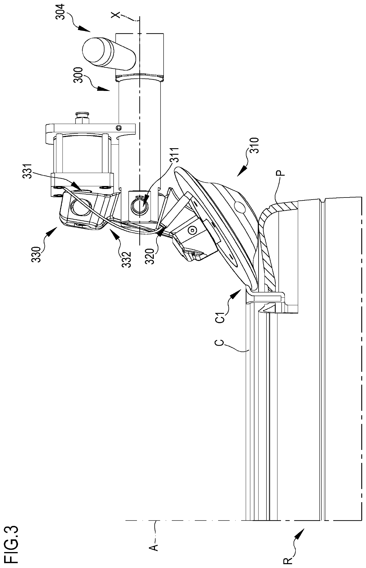
[0116]The base 100 has, joined thereto, a frame 200 having an upright 210 extending mainly at right angles with respect to the support surface of the base. In the figure, the upright 210 exten...


PUM


Abstract

Tyre-removal apparatus comprising a base having a support for receiving and rotating the wheel. A frame having an upright with a longitudinal axis substantially parallel to an axis of rotation of the wheel is joined to the base of the tyre-removal apparatus. A support arm is associated with the upright and is movable in a direction substantially parallel to the axis of rotation of the wheel. A tool for operating on the wheel is mounted on the support arm. An actuator is able to move the support arm along the direction substantially parallel to the axis of rotation of the wheel. At least one sensor, able to detect at least one parameter representing contact between the tool and the wheel, is associated with said actuator. Said at least one sensor is operationally connected to a control unit able to control the actuator and/or at least one further actuator, associated with the support arm, so as to move the tool along a trajectory determined by the control unit, depending on the at least one parameter representing the contact between the tool and the wheel.

Description

[0001]In the name of: Snap-on Equipment S.r.I., a company of Italian nationality with head office in Correggio (RE).FIELD OF THE INVENTION[0002]The present invention relates to an apparatus for mounting a tyre on a wheel rim and / or for removing a tyre from a wheel rim of a vehicle, generally known as a tyre-removal apparatus or machine. Also included within the scope of the present invention is a method for removing a tyre from a wheel rim of a vehicle, which can be performed by means of a tyre-removal apparatus according to the present invention.Present State of the Art[0003]The wheels of vehicles are generally composed of a rim and a tyre mounted on it. Tyre-removal apparatus are generally used in car repair workshops in order to remove the tyres from the rims and / or to mount said tyres on respective rims.[0004]Before being able to remove a tyre from a rim it is required to perform so-called bead breaking of the tyre, namely it is required to obtain the complete separation of both...

Claims


Application Information

Patent Timeline
IPC IPC(8): B60C25/05
CPCB60C25/0548B60C25/0581B60C25/13
Inventor SOTGIU, PAOLO
Owner SNAP ON EQUIP
Why Eureka
Try Eureka