Combustion chamber comprising means for cooling an annular casing zone downstream of a chimney

a combustion chamber and annular casing technology, applied in the field of combustion chambers, can solve the problems of chimney and penetrating parts, affecting the efficiency of cooling a zone of the annular casing located immediately downstream of the chimney, and affecting the efficiency of cooling of the annular casing zone, etc., to achieve the effect of simple, economical and efficien

Pending Publication Date: 2022-07-28
SN DETUDE & DE CONSTR DE MOTEURS DAVIATION S N E C M A
View PDF15 Cites 0 Cited by
  • Summary
  • Abstract
  • Description
  • Claims
  • Application Information

AI Technical Summary

Benefits of technology

[0014]The invention has in particular for purpose to provide a simple, economical and efficient solution to this problem, making it possible to avoid at least partially the disadvantages described hereinabove.

Problems solved by technology

However, in the cases where the annular casing is provided with a chimney intended for the passage of a penetrating part, such as a spark plug, through the annular casing, the chimney and the penetrating part degrade the efficiency of the cooling of a zone of the annular casing located immediately downstream of this chimney.
Indeed, the penetrating part constitutes, within the inner volume of the combustion chamber, an obstacle that interrupts the parietal film of air.
Finally, outside the combustion chamber, the chimney also constitutes an obstacle to the flow of cool air circulating in the bypass space of the combustion chamber and supplying the microperforations.
These solutions are however not optimal regarding the cooling of the zone located immediately downstream of a chimney.
The supplying with air of these microperforations is however not optimal due to the fact that the chimney masks the microperforations with regards to the flow of air circulating in the bypass space of the combustion chamber.

Method used


Image

  • Combustion chamber comprising means for cooling an annular casing zone downstream of a chimney
  • Combustion chamber comprising means for cooling an annular casing zone downstream of a chimney
  • Combustion chamber comprising means for cooling an annular casing zone downstream of a chimney

Examples


Embodiment Construction

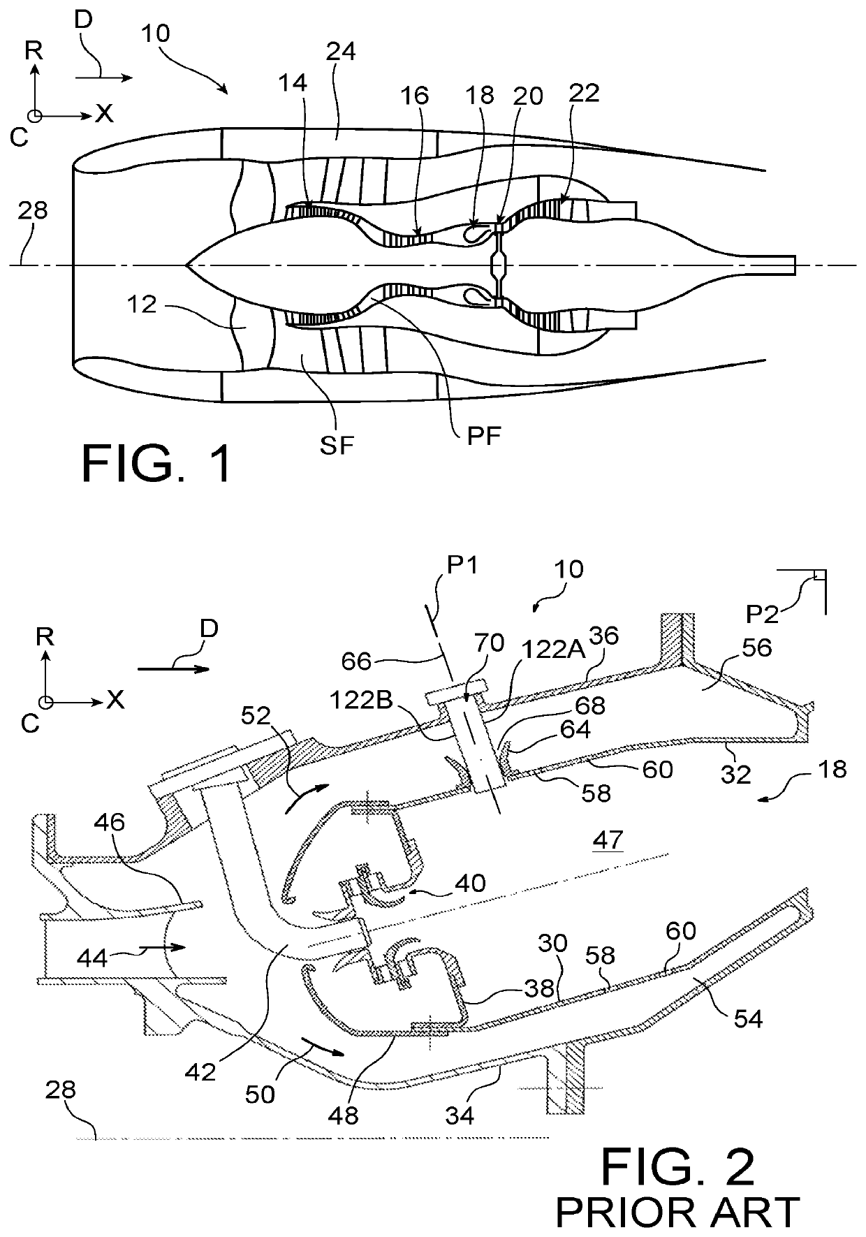
[0040]The FIG. 1 shows a turbomachine 10 for an aircraft, including in general a fan 12 intended for the aspiration of a flow of air being divided downstream of the fan into a primary flow circulating in a flow channel for primary flow, hereinafter called primary duct PF, within a gas generator, and a secondary flow that bypasses this gas generator in a flow channel for secondary flow, hereinafter called secondary duct SF.

[0041]The turbomachine is for example a bypass turbo turbine engine. The gas generator thus includes, generally, a low-pressure compressor 14, a high-pressure compressor 16, a combustion chamber 18, a high-pressure turbine 20 and a low-pressure turbine 22. The respective rotors of the high-pressure compressor and of the high-pressure turbine are connected by a shaft called “high-pressure shaft”, while the respective rotors of the low-pressure compressor and of the low-pressure turbine are connected by a shaft called “low-pressure shaft”, in a manner known per se. T...


PUM


Abstract

A combustion chamber for a turbomachine including an annular casing delimiting an inner volume of the combustion chamber and provided with a chimney extending to the outside of the inner volume and delimiting a passage for a penetrating part, and a bushing mounted floating on the chimney, further includes: a main air collection chamber open to the upstream arranged facing the downstream portion of the chimney; and a through-opening of the annular casing, connecting the inner volume to the main air collection chamber. The air collected by the main air collection chamber is injected into the inner volume via the through-opening and can cool an annular casing zone downstream of the chimney.

Description

TECHNICAL FIELD[0001]The present invention relates to the field of combustion chambers of turbomachines, in particular turbomachines used for the propulsion of aircraft.[0002]The invention relates more particularly to a combustion chamber comprising at least one annular casing delimiting an inner volume of the combustion chamber and provided with a chimney extending to the outside of the inner volume and delimiting a passage for a penetrating part through the annular casing, and, possibly, a bushing mounted floating on the chimney.PRIOR ART[0003]The internal temperature of combustion chambers is such that it is in general necessary to cool the annular casings that delimit the inner volume of these combustion chambers.[0004]A common solution to limit the heating of such an annular casing consists of circulating a relatively cool film of air along the annular casing, within the inner volume of the combustion chamber.[0005]Such a parietal film of air is in general formed by means of a ...

Claims


Application Information

Patent Timeline
Patent Type & Authority Applications(United States)
IPC IPC(8): F23R3/06F23R3/50F23R3/00
CPCF23R3/06F23R3/60F23R3/002F23R3/50F23R2900/03042F02C7/266F05D2260/202Y02T50/60
Inventor LEPAROUX, JULIEN MARC MATTHIEUPIEUSSERGUES, CHRISTOPHE
Owner SN DETUDE & DE CONSTR DE MOTEURS DAVIATION S N E C M A
Why Eureka
Try Eureka