Aft aerodynamic fairing with improved thermal resistance for a pylon for attaching an aircraft propelling assembly

a technology of aerodynamic fairing and thermal resistance, which is applied in the direction of machines/engines, manufacturing tools, transportation and packaging, etc., can solve the problems of increased mechanical stress and increased combustion gas temperature, and achieve the effect of simple implementation

Active Publication Date: 2015-02-17
AIRBUS OPERATIONS (SAS)
View PDF47 Cites 2 Cited by
  • Summary
  • Abstract
  • Description
  • Claims
  • Application Information

AI Technical Summary

Benefits of technology

[0017]One object of the invention is in particular to provide a simple, economical and efficient solution to these problems, allowing to avoid at least partly the abovementioned drawbacks.
[0028]This characteristic enables stresses induced by the differential heat expansion, in this secondary sliding direction, of the materials forming the floor with respect to the materials making up the caisson structure, to be reduced.
[0043]Besides the advantages described above in connection with the fairing, this method has the advantage to be particularly simple to be implemented.

Problems solved by technology

In a manner known to those skilled in the art, the secondary structures are different from the rigid structure in that they are not intended to ensure transfer of strains from the engine to the aircraft aerofoil.
This increase in combustion gas temperature raises numerous problems in particular with respect to heat resistance of materials forming the heat-shield floor and differential heat expansion of these materials with respect to materials making up the fairing caisson structure.
The increase in the differential heat expansion of these materials leads in particular to an increase in mechanical stresses undergone by the devices for splicing this floor to the abovementioned caisson structure.

Method used


Image

  • Aft aerodynamic fairing with improved thermal resistance for a pylon for attaching an aircraft propelling assembly
  • Aft aerodynamic fairing with improved thermal resistance for a pylon for attaching an aircraft propelling assembly
  • Aft aerodynamic fairing with improved thermal resistance for a pylon for attaching an aircraft propelling assembly

Examples


Embodiment Construction

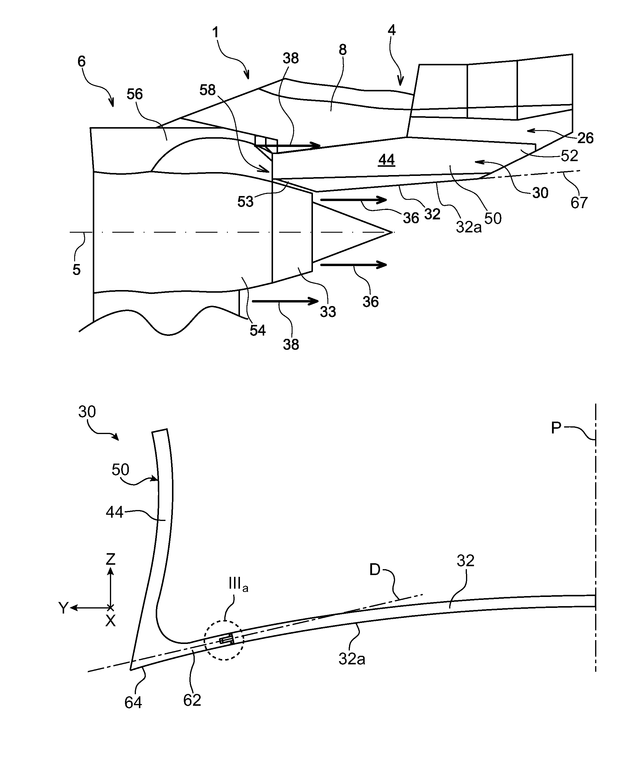
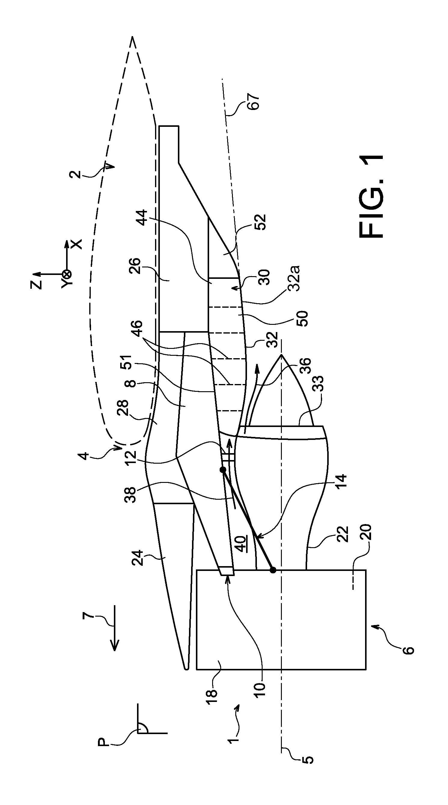
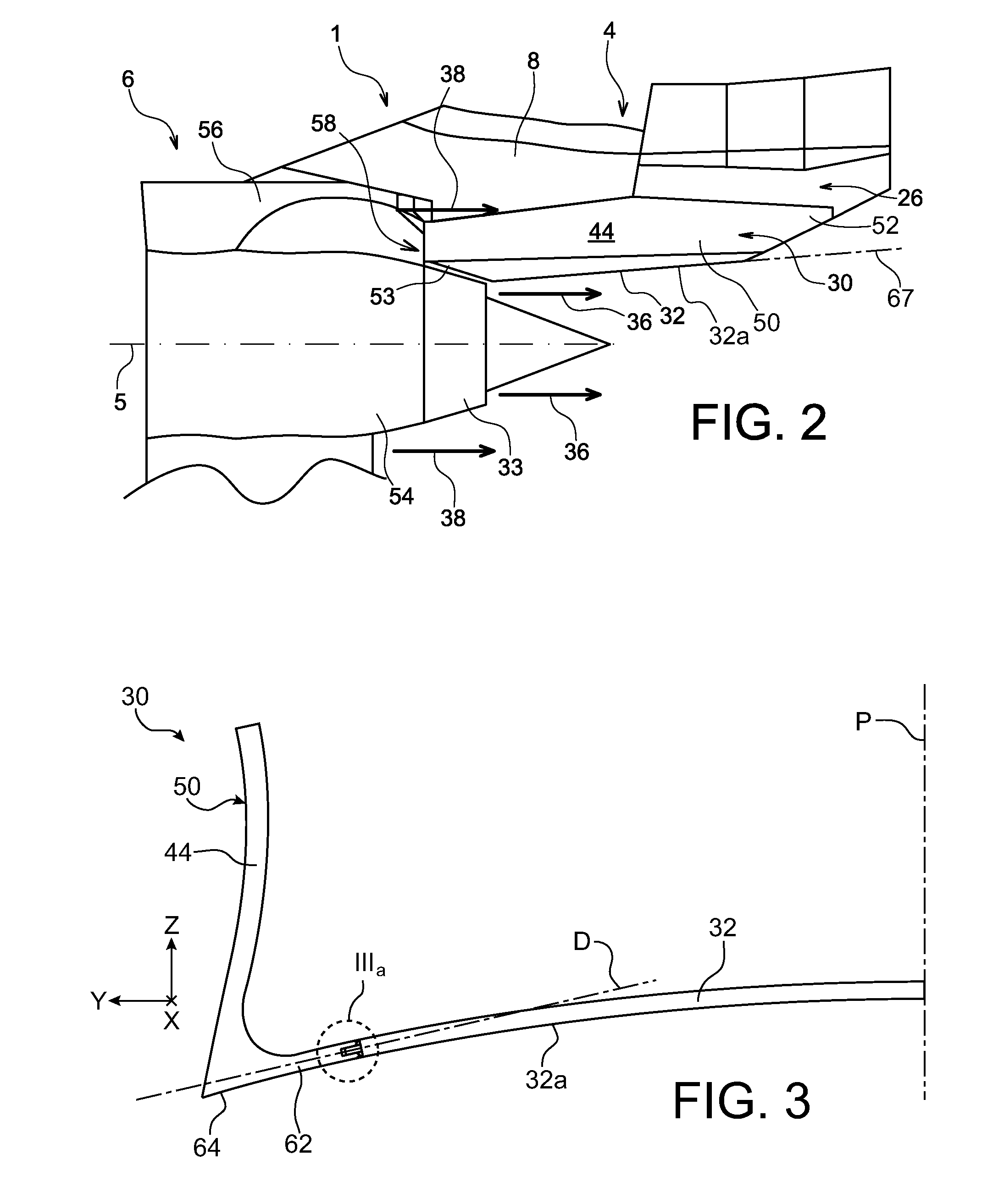
[0052]FIG. 1 illustrates a propelling assembly 1 for an aircraft according to a first preferred embodiment of the present invention, intended to be fastened under an aircraft wing 2, this propelling assembly 1 including an attaching pylon 4, as well as a turbofan engine 6 attached under this attaching pylon 4.

[0053]As a whole, the attaching pylon 4 includes a rigid structure 8, also called primary structure, carrying elements for attaching the engine 6, these attaching elements having a plurality of engine fasteners 10, 12, as well as a device 14 for recovering thrust strains generated by the turbojet engine 6.

[0054]The attaching pylon 4 includes another series of fasteners (not shown) assembled onto the rigid structure 8 and enabling this propelling assembly 1 to be suspended under the wing 2 of the aircraft.

[0055]Furthermore, the propelling assembly 1 is intended to be surrounded by a nacelle (not visible in FIG. 1).

[0056]In the entire description that follows, by convention, X de...


PUM

PropertyMeasurementUnit
temperaturesaaaaaaaaaa
thermal resistanceaaaaaaaaaa
thrust strainsaaaaaaaaaa

Abstract

An aft aerodynamic fairing for a pylon for attaching an aircraft propelling assembly, including a caisson structure, a heat-shield floor, as well as a support structure for this floor comprising linking parts arranged to link two side edges of this floor to the caisson structure. The linking parts of each side edge of the floor are configured so as to allow travelling motion of the side edge relative to the caisson structure in a corresponding direction included in a plane orthogonal to a longitudinal direction of the fairing. The linking parts form a sliding link between the floor and the caisson structure, reducing the stresses induced by the deformations of these elements in use.

Description

CROSS-REFERENCES TO RELATED APPLICATIONS[0001]This application claims the benefit of the French patent application No. 12 52745 filed on Mar. 27, 2012, the entire disclosures of which are incorporated herein by way of reference.BACKGROUND OF THE INVENTION[0002]The present invention relates to the field of pylons for attaching aircraft engines and more precisely relates to the improvement in the thermal resistance of an aft aerodynamic fairing of such an attaching pylon.[0003]This kind of attaching pylon, also called engine mounting structure (EMS) enables an engine to be suspended below the aircraft aerofoil, this engine to be mounted above the same aerofoil, or even this engine to be assembled at the rear part of the aircraft fuselage.[0004]The invention can be used on any kind of aircraft equipped with turbojet engines or turbo-propellers, or even any other kind of turbine engine.[0005]An attaching pylon is generally provided to be the linking interface between a turbine engine an...

Claims


Application Information

Patent Timeline
Patent Type & Authority Patents(United States)
IPC IPC(8): B64D27/00B64D29/02B64D29/06B64D33/04
CPCB64D29/06B64D29/02B64D33/04Y10T29/49826
Inventor RAISON, FABIENROMANI, STEPHANEBELL, LAURENT
Owner AIRBUS OPERATIONS (SAS)
Why Eureka
Try Eureka