Eureka AIR delivers breakthrough ideas for toughest innovation challenges, trusted by R&D personnel around the world.

System and method for repairing a generator main lead

Active Publication Date: 2022-08-04
SIEMENS ENERGY INC
View PDF5 Cites 1 Cited by
  • Summary
  • Abstract
  • Description
  • Claims
  • Application Information

AI Technical Summary

Benefits of technology

The patent describes a new design for a turbogenerator stator that improves cooling and efficiency. It includes a stator core, stator bars, a parallel ring, and two lead tubes that connect the stator bars and the parallel ring. The design allows for greater fluid communication and electrical connection, resulting in improved performance and reliability. The invention also includes a method for repairing the stator to further enhance its performance.

Problems solved by technology

The use and arrangement of the cooling for these generators often includes complicated flow paths and arrangements that are exposed to operating conditions that can lead to damage and leakage.

Method used


Image

  • System and method for repairing a generator main lead
  • System and method for repairing a generator main lead
  • System and method for repairing a generator main lead

Examples


Embodiment Construction

[0016]Before any embodiments of the invention are explained in detail, it is to be understood that the invention is not limited in its application to the details of construction and the arrangement of components set forth in this description or illustrated in the following drawings. The invention is capable of other embodiments and of being practiced or of being carried out in various ways. Also, it is to be understood that the phraseology and terminology used herein is for the purpose of description and should not be regarded as limiting.

[0017]Various technologies that pertain to systems and methods will now be described with reference to the drawings, where like reference numerals represent like elements throughout. The drawings discussed below, and the various embodiments used to describe the principles of the present disclosure in this patent document are by way of illustration only and should not be construed in any way to limit the scope of the disclosure. Those skilled in the...


PUM


Abstract

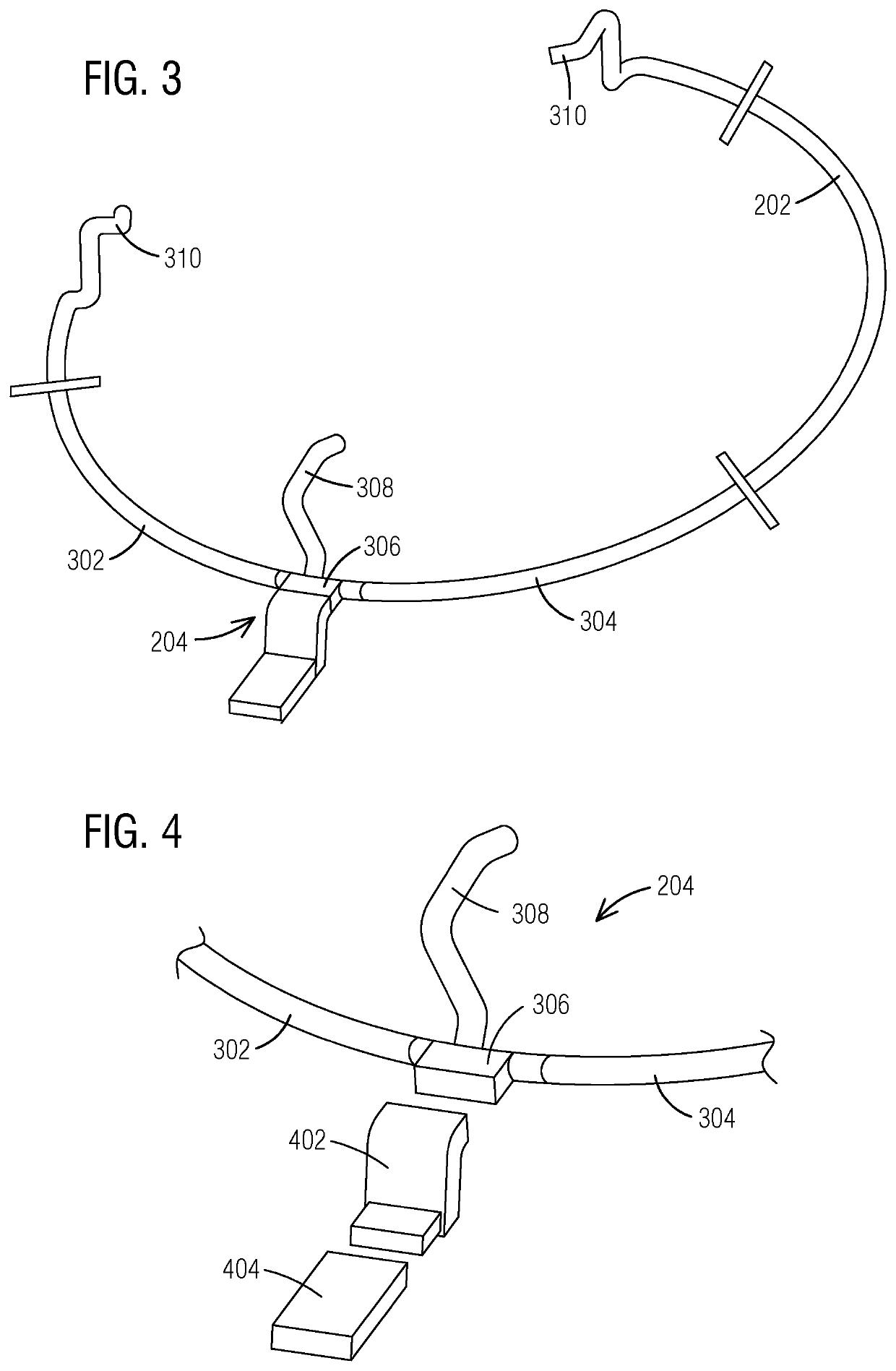
A turbogenerator includes a stator core defining a first end and a second end, a plurality of stator bars disposed within the stator core, each stator bar including a coolant flow path, and a parallel ring having a first segment and a second segment separate from the first segment. The parallel ring is coupled to the first end of the stator core and is arranged to electrically connect the plurality of stator bars and to fluidly connect the coolant flow paths of the plurality of stator bars. A tang includes a main chamber, a first coolant opening, a second coolant opening, and a distribution channel that fluidly interconnects the main chamber, the first coolant opening, and the second coolant opening. A first lead tube has a first lead end connected to the first coolant opening and a second lead end connected to the first segment, and a second lead tube separate from the first lead tube has a first lead end connected to the second coolant opening and a second lead end connected to the second segment. The plurality of stator bars, the parallel ring, the tang, the first lead tube, and the second lead tube cooperate to define a portion of a circuit and a portion of a cooling path.

Description

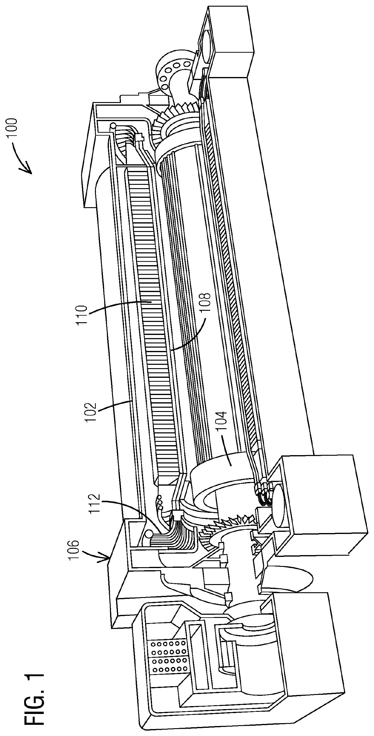
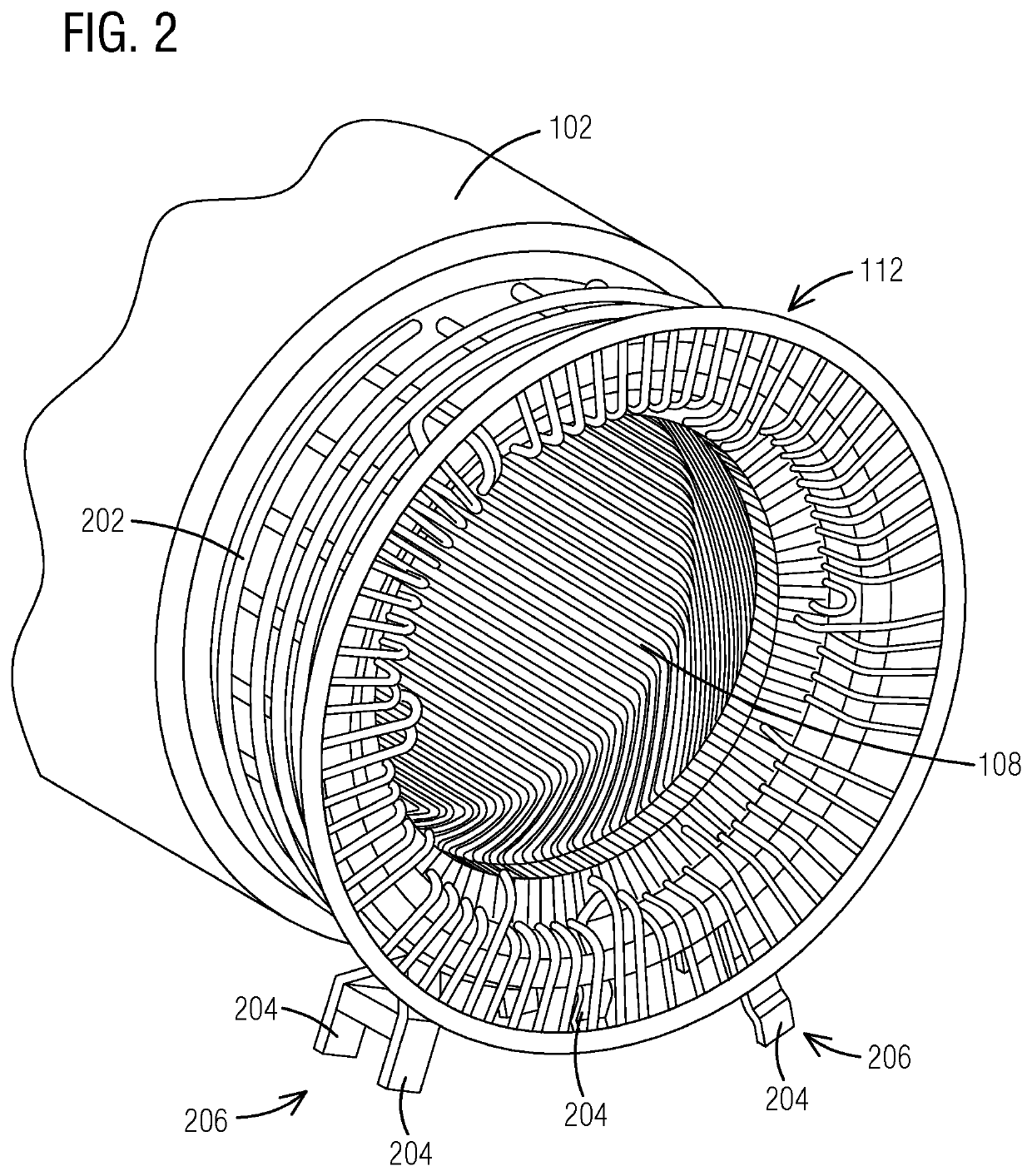
BACKGROUND[0001]Turbogenerators used for power generation often employ cooling systems to cool both the rotor and the stator of the generator. In some two-pole and four-pole generators, liquid or water cooling is used to cool the stator. The use and arrangement of the cooling for these generators often includes complicated flow paths and arrangements that are exposed to operating conditions that can lead to damage and leakage.BRIEF SUMMARY[0002]In one aspect, a turbogenerator includes a stator core defining a first end and a second end, a plurality of stator bars disposed within the stator core, each stator bar including a coolant flow path, and a parallel ring having a first segment and a second segment separate from the first segment. The parallel ring is coupled to the first end of the stator core and is arranged to electrically connect the plurality of stator bars and to fluidly connect the coolant flow paths of the plurality of stator bars. A tang includes a main chamber, a fir...

Claims


Application Information

Patent Timeline
IPC IPC(8): H02K3/24H02K7/18H02K9/197H02K15/00F01D15/10
CPCH02K3/24H02K7/1823F01D15/10H02K15/0006H02K9/197H02K3/50H02K3/22H02K2203/09F05D2220/7642F01D25/12H02K13/04H02K15/02H01R43/002H01R43/14H02K9/28H02K15/0093
Inventor EBERHARDT, NICHOLAS
Owner SIEMENS ENERGY INC
Why Eureka
Eureka Blog
Learn More