
Support Jig for Assembling Elevator Car

Active Publication Date: 2022-08-11
FUJITEC CO LTD
View PDF6 Cites 0 Cited by
  • Summary
  • Abstract
  • Description
  • Claims
  • Application Information

AI Technical Summary

Benefits of technology

The present invention provides a support jig for assembling an elevator car that can be easily installed to the car rail. The technical effect is to provide a convenient and efficient tool for elevator car assembly.

Problems solved by technology

Therefore, the mounting operation of the car frame support bases 100 to the car rail 103 in the limited work space in the shaft was difficult to perform.

Method used


Image

  • Support Jig for Assembling Elevator Car
  • Support Jig for Assembling Elevator Car
  • Support Jig for Assembling Elevator Car

Examples


Embodiment Construction

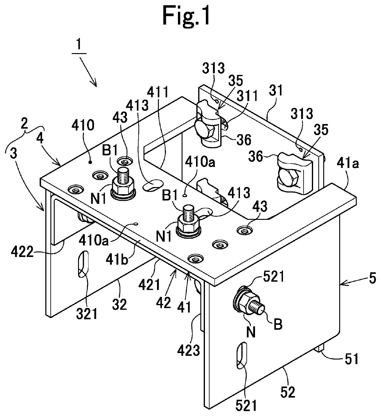
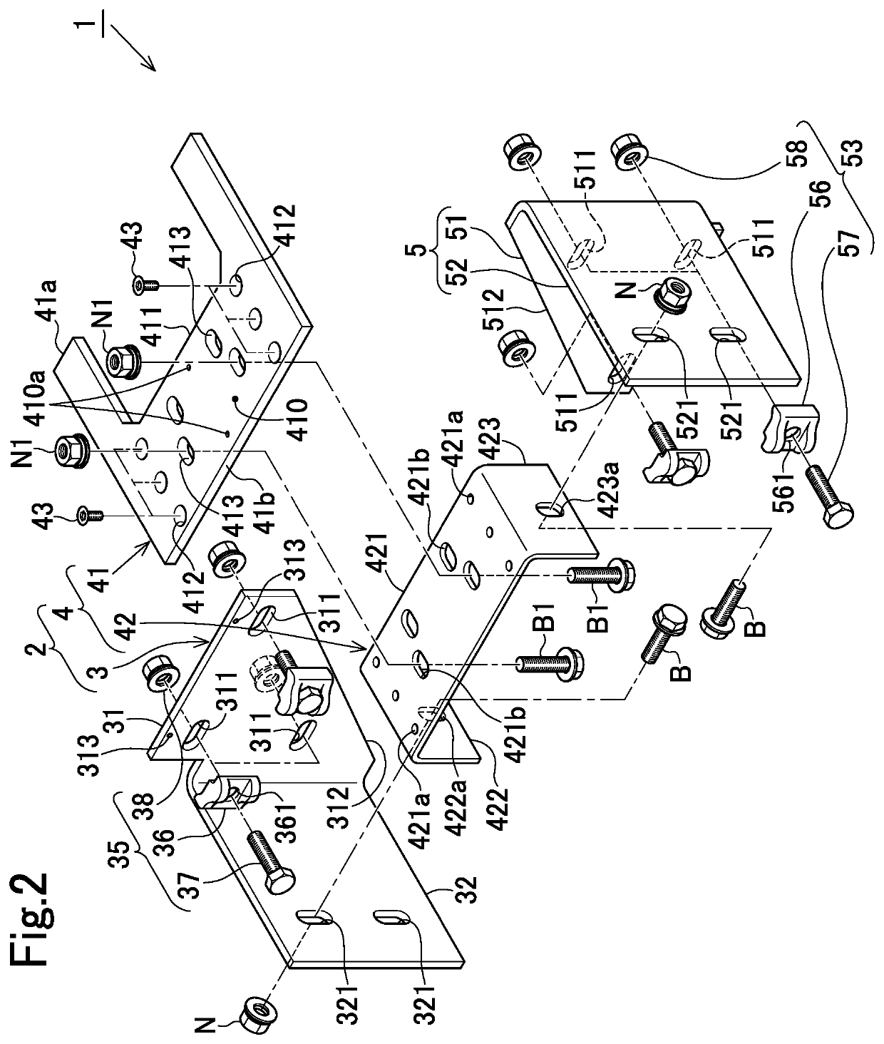
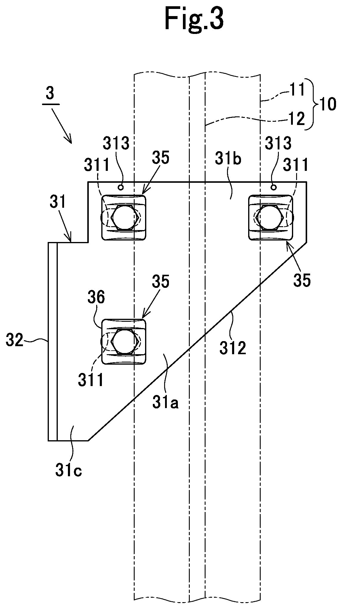
[0029]Hereinafter, a description will be given on one embodiment of the present invention with reference to FIG. 1 to FIG. 9.

[0030]The support jig for assembling an elevator car of this embodiment (hereinafter, also simply referred to as “the support jig”) is detachably fixed to a car rail that vertically extends in a shaft and guides the elevator car, and is used for assembling the elevator car in the shaft. Hereinafter, a description will be given on the car rail to which the support jig is detachably fixed, and then a description will be given on a specific configuration of the support jig. Also in the description herein, the directional terms such as top, bottom, right, left, etc. when referring to the support jig and the respective configurations are respectively used on the basis of the state in which the support jig is attached to the car rail (see FIG. 7 and FIG. 8).

[0031]A pair of car rails are provided for one car in an elevator shaft. The pair of car rails are disposed on...


PUM


Abstract

The present invention provides a support jig for assembling an elevator car including; a first member including a first member body configured to be detachably fixed to a car rail having a front surface and a rear surface and vertically extending in a shaft to guide the ascending and descending of the elevator car on the front surface side, and a mount part on which a component of the elevator car is mountable; and a second member including a second-member fixing part configured to be detachably fixed to the car rail, and a support part extending from the second-member fixing part and configured to support the mount part of the first member from below.

Description

CROSS-REFERENCE TO RELATED APPLICATION[0001]This application claims priority to Japanese Patent Application No. 2021-017186 filed Feb. 5, 2021, the disclosure of which is hereby incorporated by reference in its entirety.BACKGROUND OF THE INVENTIONField of the Invention[0002]The present invention relates to a support jig for assembling an elevator car detachably fixed to a car rail for use when an elevator car is assembled in a shaft.Description of Related Art[0003]Conventionally, there is known a car frame support base (a support jig for assembling an elevator car) used by being fixed to a car rail when an elevator car is assembled in a shaft (see JP S56-23913 B). Specifically, as shown in FIG. 10, a car-frame support base 100 includes a mounting member 104 configured to be fixed to a car rail 103 by a plurality of clips 101 and a plurality of bolts 102, a car frame receiving seat 105 formed integrally with the mounting member 104, a member 107 detachably fixed to the mounting membe...

Claims


Application Information

Patent Timeline
IPC IPC(8): B66B19/04B66B19/00B66B11/02
CPCB66B19/04B66B11/0226B66B19/002B66B19/00
Inventor KASHIWAKURA, HIROSHI
Owner FUJITEC CO LTD
Learn More