
Operator's cabin having a protective grid

a protective grid and operator technology, applied in the direction of transportation and packaging, pedestrian/occupant safety arrangements, vehicular safety arrangements, etc., can solve the problems of disadvantageous protective grids at the front and roof regions, affecting the safety of passengers, and requiring considerable resources

Pending Publication Date: 2022-08-18
LIEBHERR FRANCE
View PDF3 Cites 0 Cited by
  • Summary
  • Abstract
  • Description
  • Claims
  • Application Information

AI Technical Summary

Benefits of technology

The invention aims to provide an operator's cabin with a roof and front protective grid that can be moved out of their protective positions to reduce the loading height of the cabin or work machine. The grids can be stacked on top of each other, making efficient use of available space. The grids can also be pivoted or moved by a hinge-like connection to the cabin to further reduce the total height. The roof and front grids can be conveyed into a region behind the cabin for storage while maintaining their alignment. The use of parallelogram linkages connected to the grids enables desired movement of the grids with respect to the cabin.

Problems solved by technology

It can in particular occur under adverse conditions of use that larger rocks or the like fall down so that a danger to the operator can arise.
The protective grids at the front side and in the roof region are disadvantageous in some situations, however, since the front grid arranged in front of the front windshield, for example, obstructs the view of the operator on the actuation of the work machine.
The roof grid is here as a rule also designed as dismantlable since it unnecessarily increases the structure height on a transport of the work machine and unnecessarily complicates a loading of the work machine.
It is problematic with a dismantling or fitting of a protective grid that considerable resources are always required in this respect.
In addition, it represents a time-consuming and dangerous task since it has to be carried out at the outer side of the operator's cabin at a height of a plurality of meters.
Smaller collisions with the operator's cabin or with components attached thereto also frequently occur on the attachment or removal of protective grids so that the desired change of a protective grid configuration brings about a large number of disadvantages.

Method used


Image

  • Operator's cabin having a protective grid
  • Operator's cabin having a protective grid
  • Operator's cabin having a protective grid

Examples


Embodiment Construction

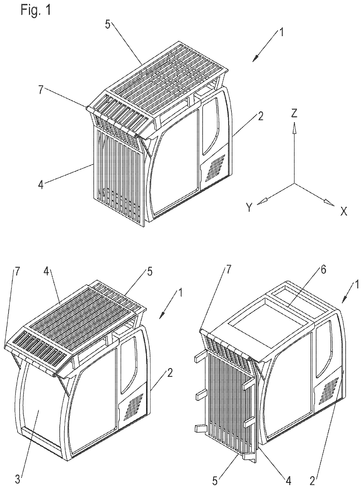
[0047]FIG. 1 shows a perspective view of an operator's cabin 1 having a housing structure 2 surrounding a workplace for an operator. This housing structure 2 typically has an access door at its left and / or right side through which the operator can enter into or exit the operator's cabin. At its front side, the housing structure 2 typically has a mount 3 for a front windshield through which the operator can look during a performance of his operating work. When carrying out hazardous work in which rocks or parts of building to be removed can fall down onto the operator's cabin, it is necessary for the increase of the safety of the operator to protect the front side of the operator's cabin with a front grid 4. The same also applies to the roof section 6 of the operator's cabin 2 that can likewise have a cutout for a roof window. It is thus made possible for an operator sitting in the operator's cabin to have a particularly good view upward so that the performance of demanding work acti...


PUM


Abstract

The invention relates to an operator's cabin of a work machine, in particular of an earth-moving machine, comprising: a housing structure that surrounds a workplace for an operator of the work machine, a front windshield at a front side of the operator's cabin, a front grid that is positioned in its protective position in front of the front windshield, and a roof grid that is positioned in its protective position above a roof section of the operator's cabin. The operator's cabin is characterized in that the front grid and the roof grid can be moved out of their respective protective positions by a rotary movement and / or a translatory movement.

Description

BACKGROUND OF THE INVENTION[0001]The present invention relates to an operator's cabin having a protective grid, in particular for operator's cabins for work machines such as earth-moving machine or the like.[0002]It is necessary in a large number of work machines to additionally reinforce the operator's cabin with protective grids so that the safety of an operator sitting in the operator's cabin is also ensured to the best possible extent in the event of an impact of falling objects that have been hurled up or of any other accident. It can in particular occur under adverse conditions of use that larger rocks or the like fall down so that a danger to the operator can arise.[0003]It is customary in the prior art for this reason to arrange protective grids in front of the front windshield and in the roof region of an operator's cabin that ensure additional protection for the operator in the operator's cabin in the aforesaid case.[0004]The protective grids at the front side and in the r...

Claims


Application Information

Patent Timeline
Patent Type & Authority Applications(United States)
IPC IPC(8): E02F9/16B62D33/06B60R21/11
CPCE02F9/163B60R21/11B62D33/0617B62D33/06B60R19/02B60R19/38
Inventor THAL, FABRICESABATY-CUGNETTI, AURÉLIENDISSER, JÉROME
Owner LIEBHERR FRANCE
Learn More