Coil mounting device and coil mounting method

Pending Publication Date: 2022-09-08
HONDA MOTOR CO LTD
View PDF2 Cites 0 Cited by
  • Summary
  • Abstract
  • Description
  • Claims
  • Application Information

AI Technical Summary

Benefits of technology

The present invention provides a device and method for mounting an annularly wound belt-shaped coil in a stator core. The device can easily and securely insert the coil into slots from the inside of the stator core. The invention allows for efficient use of the straight portions of the coil by expanding it from both sides in the axial direction of the coil winding jig. The technical effect of this invention is improved efficiency in inserting the belt-shaped coil into slots.

Problems solved by technology

However, the above-mentioned related art discloses neither a specific device nor a specific method for inserting the coil into the slots while expanding in diameter the coil inserted inside the stator core.

Method used


Image

  • Coil mounting device and coil mounting method
  • Coil mounting device and coil mounting method
  • Coil mounting device and coil mounting method

Examples


Embodiment Construction

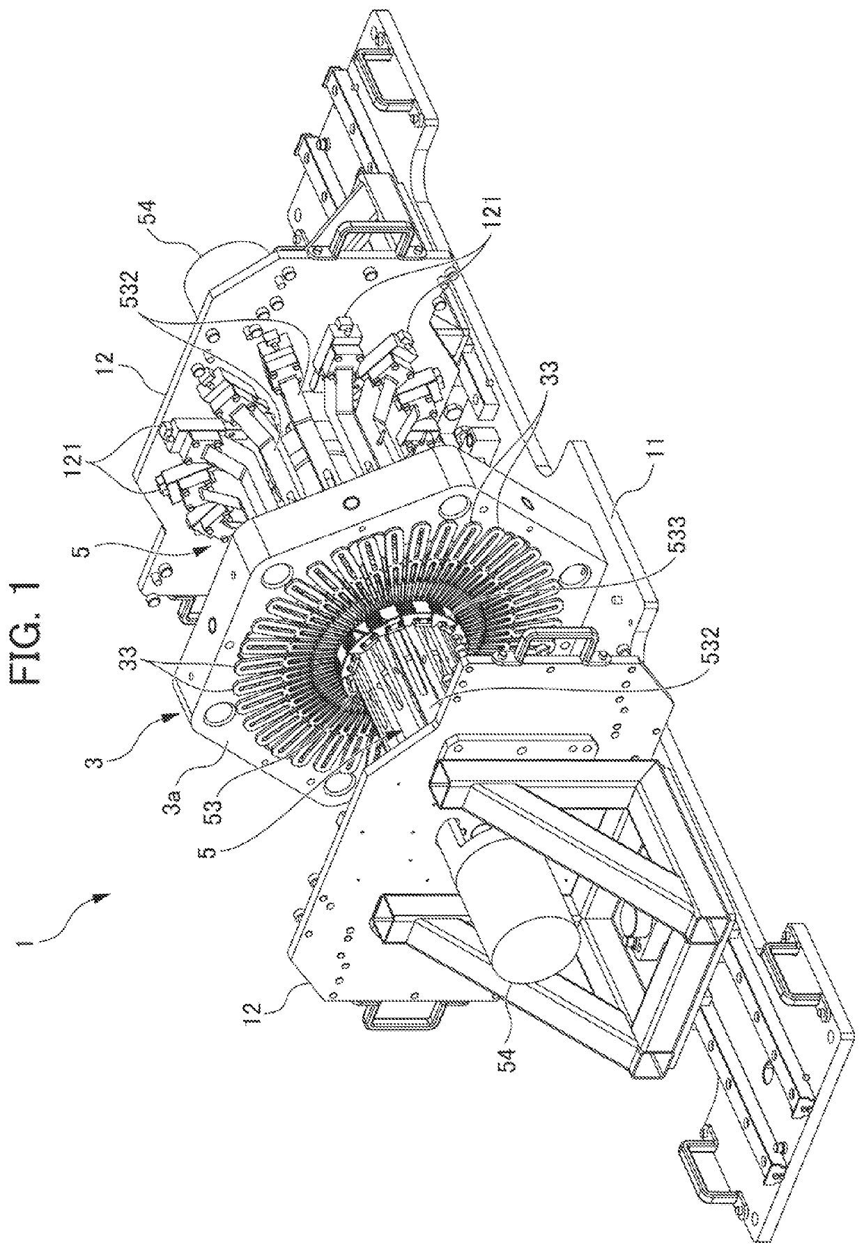
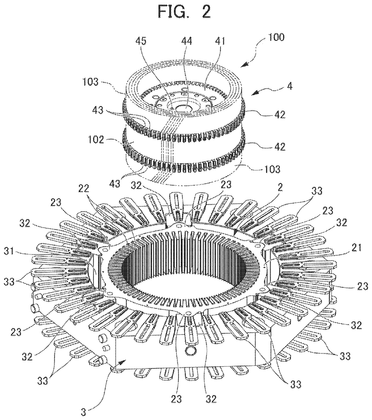
[0043]An embodiment of the present invention will be described in detail with reference to the drawings. As shown in FIGS. 1 and 2, a coil mounting apparatus 1 includes a stator core 2, a stator core fixing jig 3 for fixing the stator core 2, a coil winding jig 4 which is inserted inside the stator core 2 and winds up a belt-shaped coil 100 in an annular shape therearound, and a coil expansion mechanism 5 for expanding the belt-shaped coil 100 wound around the coil winding jig 4.

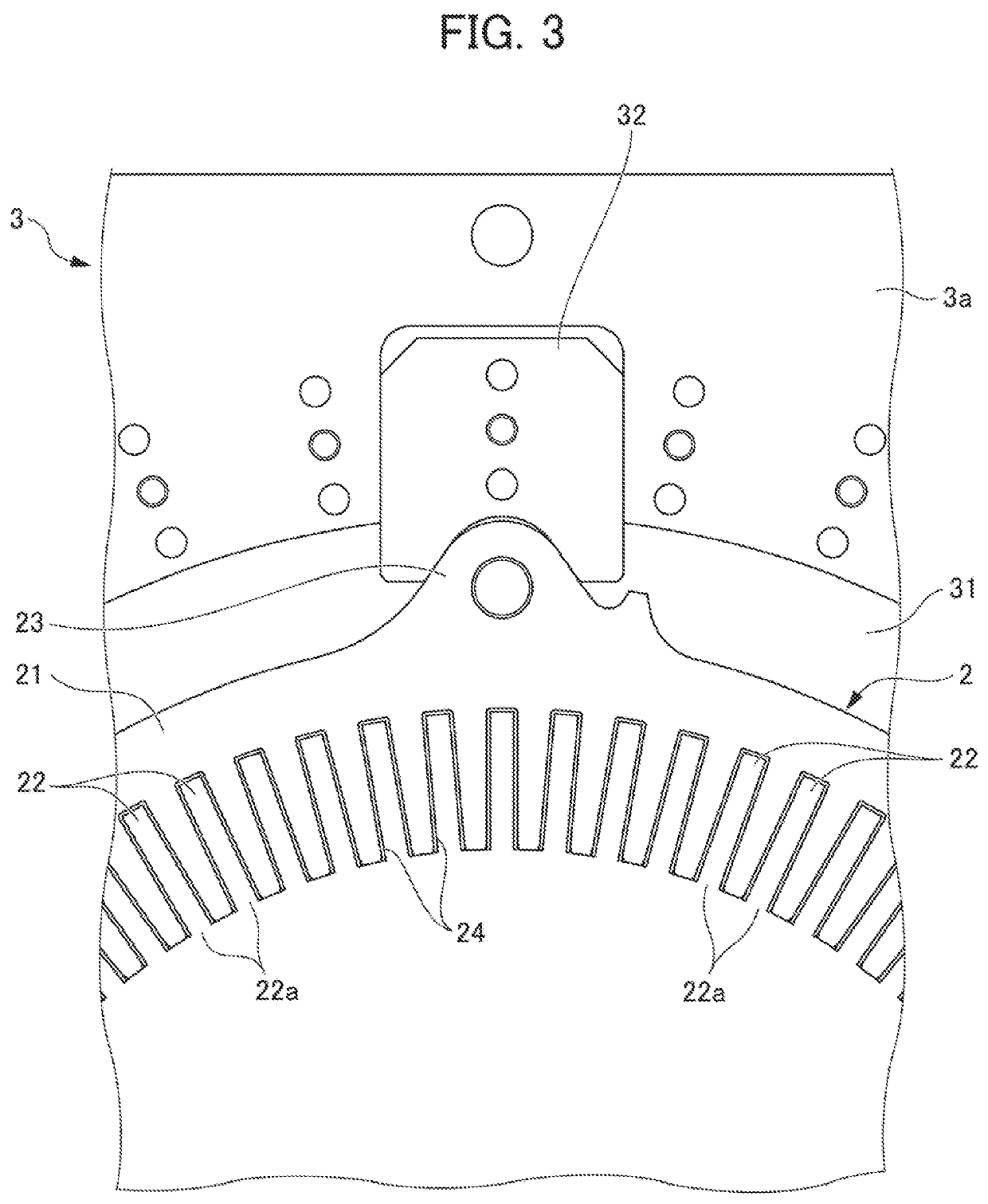
[0044]As shown in FIGS. 2 and 3, the stator core 2 includes an annular portion 21 consisting of, for example, a laminate including a plurality of thin core plates laminated together. The stator core 2 has a plurality of slots 22 penetrating therethrough in the axial direction of the stator core 2. The slots 22 are arranged radially at regular intervals in the circumferential direction of the annular portion 21, and have openings 22a that open inward in the radial direction of the annular portion 21. The stat...


PUM


Abstract

A coil mounting device includes a stator coil, a coil winding jig that has an outer diameter smaller than an inner diameter of the stator core and winds therearound a belt-shaped coil in an annular shape, a stator core fixing jig that fixes the stator core at a predetermined position and in a predetermined posture, and a coil expansion mechanism that expands the belt-shaped coil. The coil expansion mechanism includes a holder that holds the coil winding jig inside the stator core in a state where the inter-comb-teeth grooves are matched in phase with the slots, and a coil expander that expands the belt-shaped coil by pressing a portion nearer to a side end than the straight portions of the belt-shaped coil wound around the coil winding jig held by the holder so as to expand the portion, thereby inserting the straight portions into the slots.

Description

[0001]This application is based on and claims the benefit of priority from Japanese Patent Application No. 2021-034309, filed on 4 Mar. 2021, the content of which is incorporated herein by reference.BACKGROUND OF THE INVENTIONField of the Invention[0002]The present invention relates to a coil mounting device and a coil mounting method.Related Art[0003]There has been conventionally known a method for mounting an annularly wound coil in a slot of a stator core by inserting the annularly wound coil inside the stator core and moving an in-slot accommodation portion of the coil from inside toward outside with respect to slots of the stator core (for example, see Patent Document 1).[0004]In the above-mentioned related art, after the coil is wound around a cylindrical insertion jig having grooves on the outer periphery thereof and inserted inside the stator core, the coil wound around the insertion jig is expanded in diameter by an expanding jig.[0005]Patent Document 1: Japanese Patent. No...

Claims


Application Information

Patent Timeline
IPC IPC(8): H02K15/06H02K15/04H02K1/16
CPCH02K15/066H02K15/045H02K1/165H02K15/0478
Inventor OHASHI, YASUTOHIKIMA, NORIHIKO
Owner HONDA MOTOR CO LTD
Why Eureka
Try Eureka