
Lifting system

Pending Publication Date: 2022-09-15
ELEVATOR
View PDF0 Cites 0 Cited by
  • Summary
  • Abstract
  • Description
  • Claims
  • Application Information

AI Technical Summary

Benefits of technology

The present invention is a lifting system that has a control arm and a support beam for lifting a platform. The control arm has an engagement member that maintains translational movement of the platform along a vertical support rail while the support beam has a compensator to keep the platform stable. A stabilizer arm is connected to the control arm and the platform to prevent side-to-side movement. A spring is connected between the control arm and the platform to keep it biased towards the first pivot axis. The technical effects of the invention are improved stability and efficiency of the lifting platform.

Problems solved by technology

In mobile living quarters, such as trailers, campers, or recreational vehicles (RV), there is limited space.
In particular, accommodations for sleeping within the relatively limited space of an RV consume a significant portion of the available space in the RV when the occupants are awake and moving about the RV.
These mechanisms are subject to becoming entangled with bedding materials, causing personal injury, getting out of adjustment, or becoming jammed.
Other mechanisms may be difficult to use or require the use of electricity.

Method used


Image

  • Lifting system
  • Lifting system
  • Lifting system

Examples


Embodiment Construction

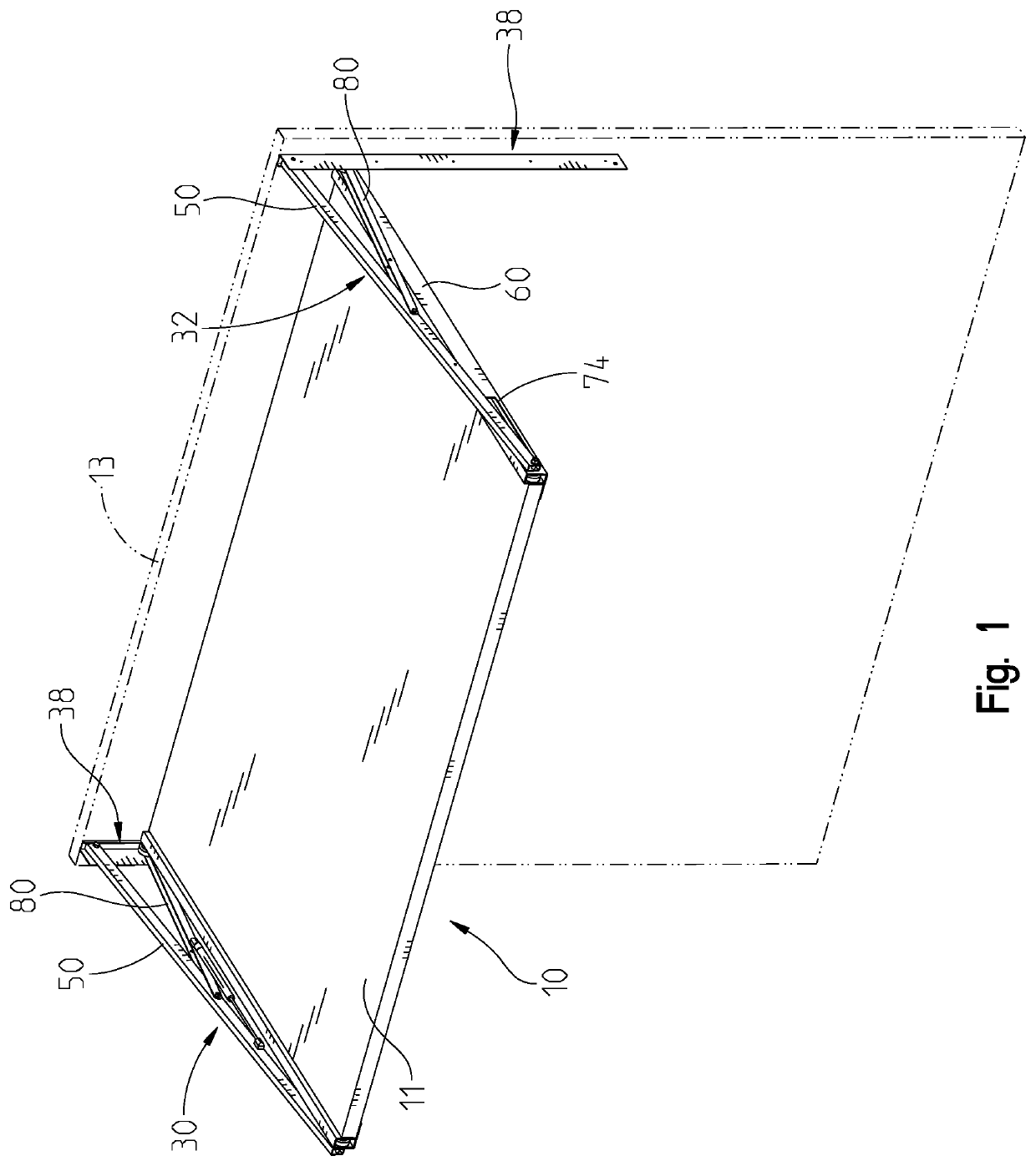
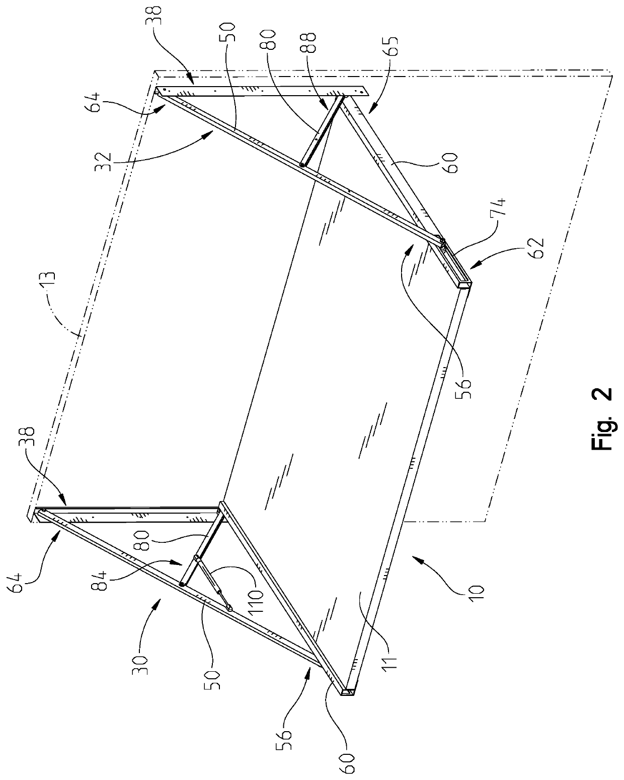
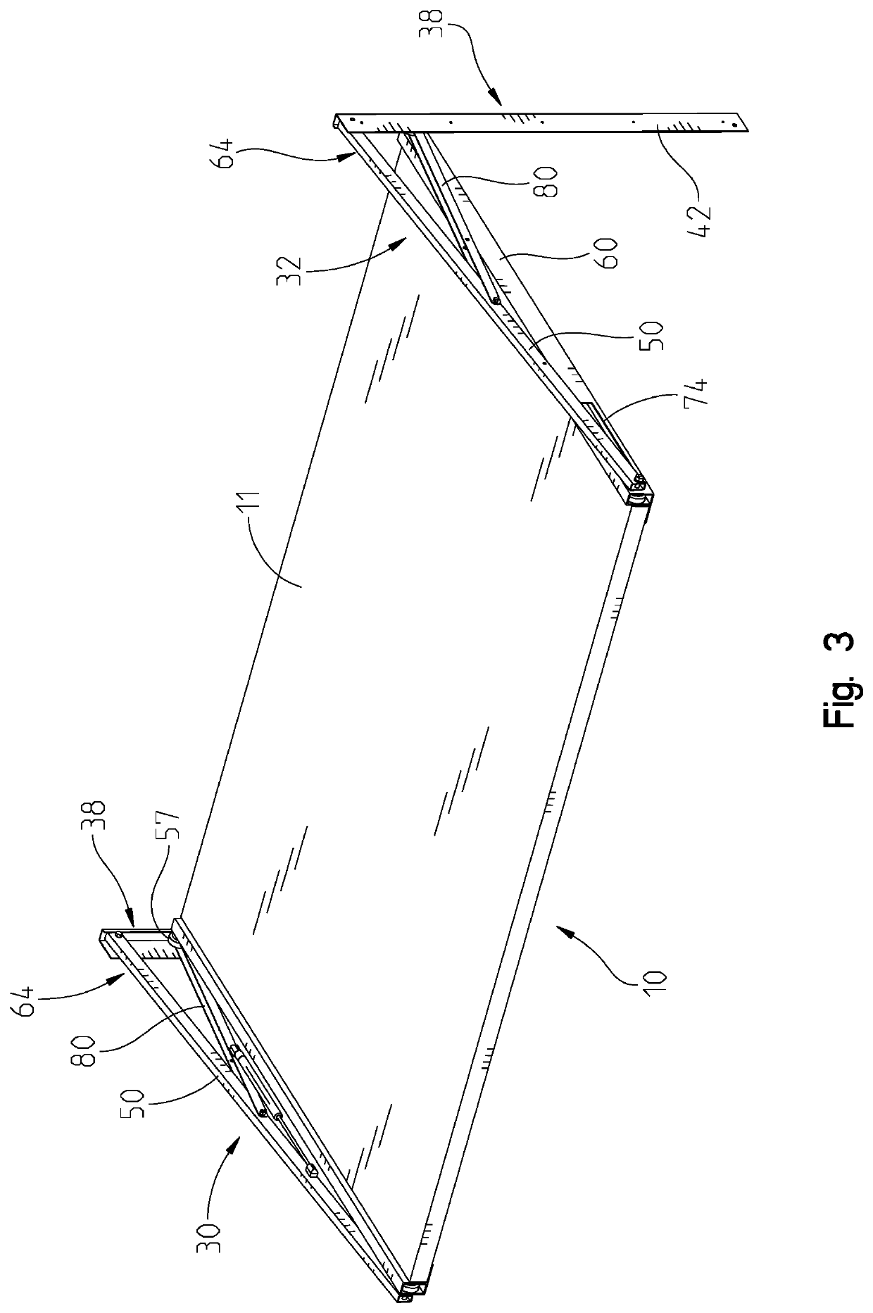
[0016]The lifting system 10 of the present invention has a lifting platform 11 that is straddled by a pair of lifting assemblies 30, 32. The left lifting assembly 30 is symmetrical with the right lifting assembly 32. FIG. 1 shows an overview of the lifting assemblies 30, 32 and the lifting platform 11 that is attached between the lifting assemblies 30, 32. As viewed in FIG. 1, the lifting system 10 is shown in its fully raised position. Each lifting assembly 30, 32 includes the same components and in some instances the components correspond to a left hand or right hand version, with those versions of the components corresponding to them being on the left hand side of the lifting platform 11 or on the right hand side of the lifting platform 11 as viewed in FIGS. 1-4. The individual components within each lifting assembly 30, 32 will be indicated with the same numbers, despite the slight variation of whether the component is used in the left lifting assembly 30 or the right lifting as...


PUM


Abstract

A lifting system for lifting a lifting platform through use of a lifting assembly. The lifting assembly having a vertical support rail and a control arm that is pivotally connected to the vertical support rail about a first pivot axis. A support beam being connected to the lifting platform the support beam having an engaging member near its proximal end that engages the vertical support rail to provide translational movement of the support beam along the vertical support rail. The control arm having an engaging member engaging the support beam at a location spaced from the vertical support rail to provide translational movement of the engaging member with respect to the support beam. A stabilizer arm is pivotally connected to the control arm and pivotally near the proximal end of the support beam. Movement of the lifting platform causing translational movement of the engagement members.

Description

CROSS-REFERENCE TO RELATED APPLICATIONS[0001]This application claims the benefit of the Provisional U.S. Patent Ser. No. 63 / 160,323, filed Mar. 12, 2021, which is incorporated herein by reference in its entirety.BACKGROUND OF THE INVENTION[0002]In mobile living quarters, such as trailers, campers, or recreational vehicles (RV), there is limited space. This creates a need for flexibility in the available space. In particular, accommodations for sleeping within the relatively limited space of an RV consume a significant portion of the available space in the RV when the occupants are awake and moving about the RV. As such, there is a need for comfortable sleeping accommodation that take a considerable amount of space within the RV to be stowed when not in use. Transforming the sleeping space to living space increases the usefulness of the interior of the RV without having dedicated areas. One way to accomplish flexibility is to have a platform that can be used for sleeping space to ver...

Claims


Application Information

Patent Timeline
IPC IPC(8): B66F7/06B66F7/28
CPCB66F7/0616B66F7/28B60P3/39
Inventor DISHER, JOHN C.
Owner ELEVATOR
Learn More