Monostable and fault-tolerant parking brake valve assembly

a technology of parking brake and assembly, which is applied in the direction of brake control system, brake components, brake systems, etc., can solve the problems of increasing residual availability, complex system, and inability to easily implement system,

Pending Publication Date: 2022-09-22
ZF CV SYST GLOBAL GMBH
View PDF0 Cites 0 Cited by
  • Summary
  • Abstract
  • Description
  • Claims
  • Application Information

AI Technical Summary

Problems solved by technology

However, if a double fault occurs, for example, which affects both the primary braking system and the redundant braking system, there is the risk that the utility vehicle can no longer be braked in a controlled manner.
However, the system is complex and thus cannot be readily implemented in every utility vehicle.
This, too, increases the residual availability.

Method used


Image

  • Monostable and fault-tolerant parking brake valve assembly
  • Monostable and fault-tolerant parking brake valve assembly
  • Monostable and fault-tolerant parking brake valve assembly

Examples


Embodiment Construction

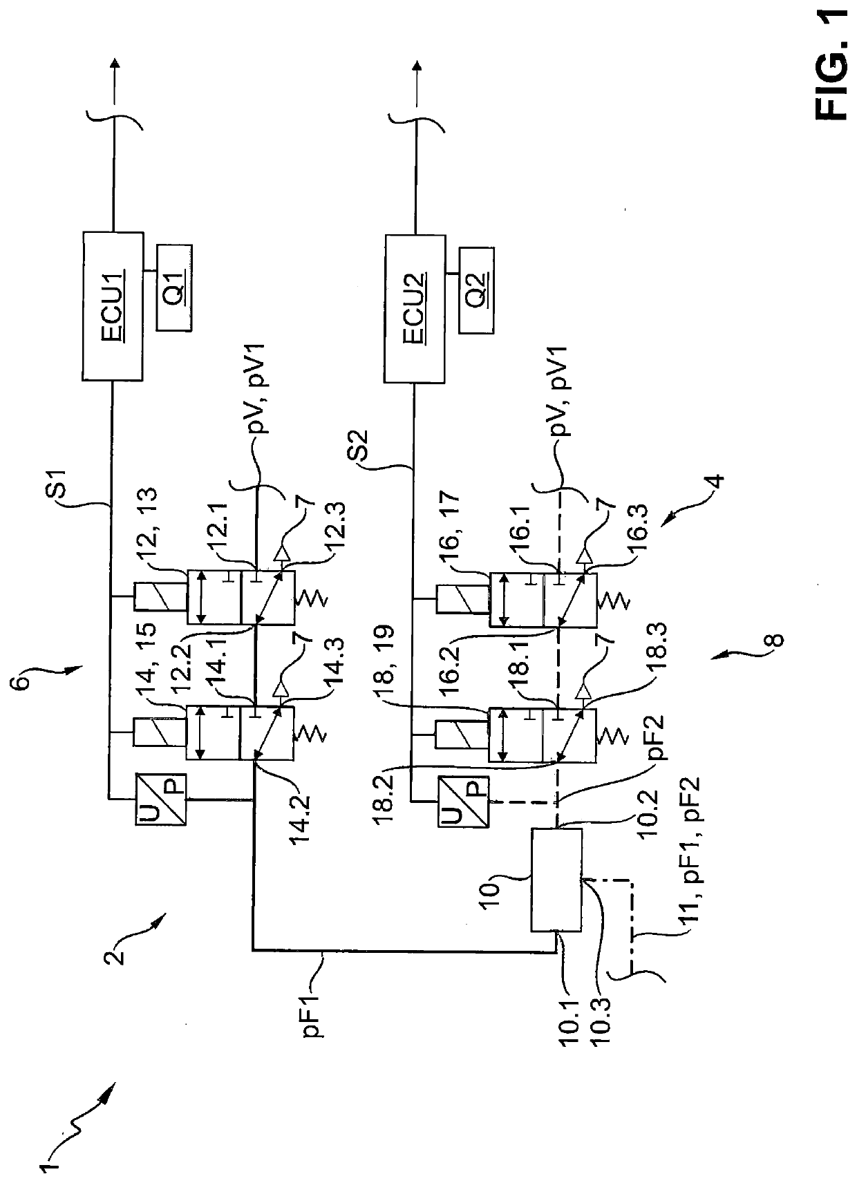
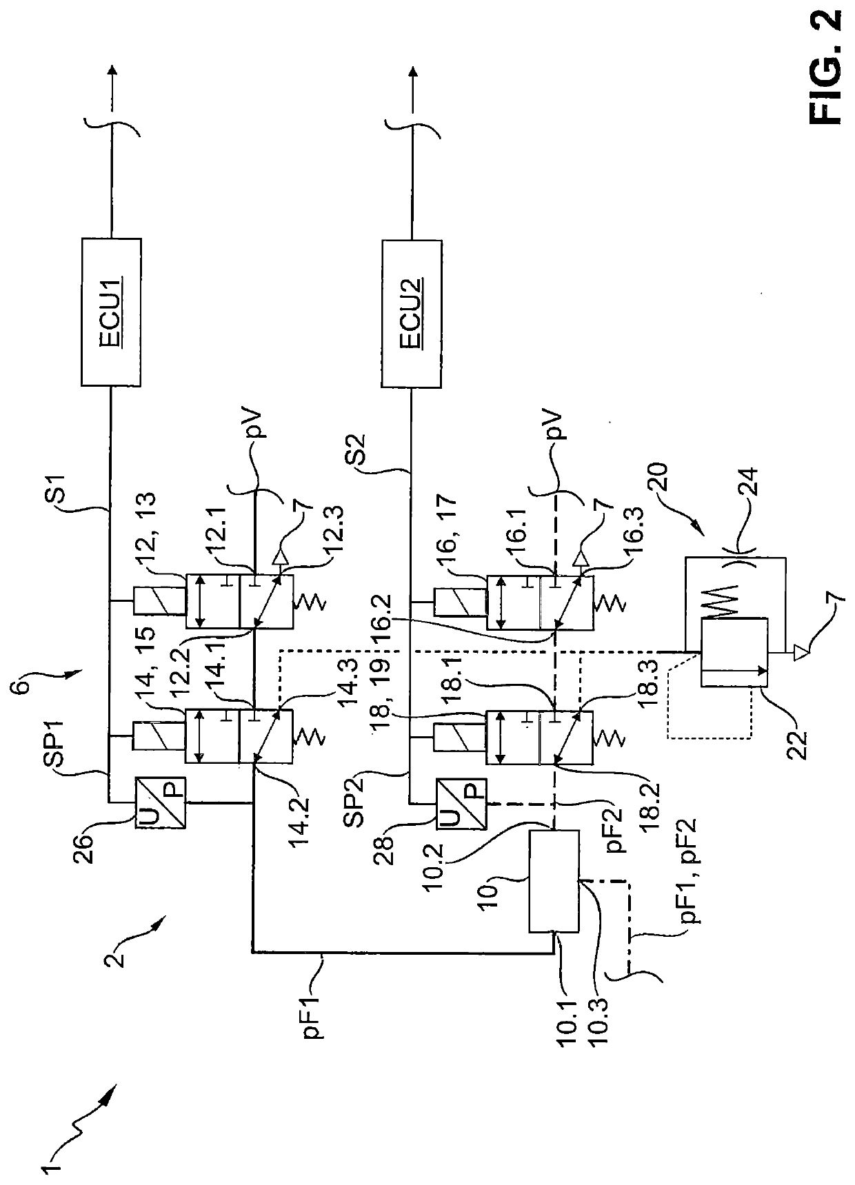
[0043]A parking brake valve assembly 1 (cf. FIG. 1) for an electronically controllable pneumatic braking system 210 (cf. FIG. 5) of a vehicle 200, in particular utility vehicle 202, has a first compressed air path 2 and a second compressed air path 4. Both the first and the second compressed air paths 2, 4 are supplied with supply pressure pV. It can also be provided that the first compressed air path 2 is supplied with a first supply pressure pV1 and the second compressed air path 4 with a second supply pressure pV2, as will be explained in more detail, for example, with regard to FIG. 5. A first monostable valve unit 6 is arranged in the first compressed air path 2 and a second monostable valve unit 8 is arranged in the second compressed air path 4. Via switching the first and second monostable valve units 6, 8, corresponding pressures can be output. Thus, by switching the first monostable valve unit 6, a first parking brake pressure pF1 can be output in the first compressed air p...


PUM


Abstract

A parking brake valve assembly for an electronically controllable pneumatic braking system of a vehicle is disclosed. The parking brake valve assembly includes: a first compressed air path which receives a supply pressure and has a first monostable valve unit for providing a first parking brake pressure, a second compressed air path which receives supply pressure and has a second monostable valve unit for providing a second parking brake pressure, and a first shuttle valve having a first shuttle valve port with the first compressed air path and receiving the first parking brake pressure, a second shuttle valve port with the second compressed air path and receiving the second parking brake pressure, and a third shuttle valve port connectable to a spring brake cylinder. The first shuttle valve outputs the higher of the first parking brake pressure and of the second parking brake pressure to the third shuttle valve port.

Description

CROSS REFERENCE TO RELATED APPLICATIONS[0001]This application is a continuation application of international patent application PCT / EP2020 / 084045, filed Dec. 1, 2020 designating the United States and claiming priority from German application 10 2019 133 011.4, filed Dec. 4, 2019, and the entire content of both applications is incorporated herein by reference.TECHNICAL FIELD[0002]The disclosure relates to a parking brake valve assembly for an electronically controllable pneumatic braking system of a vehicle, in particular utility vehicle. The disclosure furthermore relates to an electronically controllable pneumatic braking system, and to a vehicle.BACKGROUND[0003]In vehicles, in particular utility vehicles, having a pneumatic braking system, formed in particular as an electronic braking system (EBS) or anti-lock system (ABS), for the outputting of brake pressures, electropneumatic valves, for example electropneumatic switching valves connected upstream of relay valves, can be actuat...

Claims


Application Information

Patent Timeline
Patent Type & Authority Applications(United States)
IPC IPC(8): B60T13/68B60T13/38B60T13/66
CPCB60T13/683B60T13/385B60T13/662B60T2270/402B60T13/263
Inventor DIECKMANN, THOMASLÜLFING, RALPH-CARSTENVAN THIEL, JULIANWULF, OLIVER
Owner ZF CV SYST GLOBAL GMBH
Why Eureka
Try Eureka