Pressing mechanism of push switch and push switch

Pending Publication Date: 2022-09-22
ALPS ALPINE CO LTD
View PDF0 Cites 0 Cited by
  • Summary
  • Abstract
  • Description
  • Claims
  • Application Information

AI Technical Summary

Benefits of technology

[0007]A pressing mechanism of a push switch and the push switch that achieve b

Problems solved by technology

However, the conventional key switch device has a problem in that the rubber dome is thick and accordingly it is difficult to reduce the thickness of the key

Method used


Image

  • Pressing mechanism of push switch and push switch
  • Pressing mechanism of push switch and push switch
  • Pressing mechanism of push switch and push switch

Examples


Example

First Embodiment

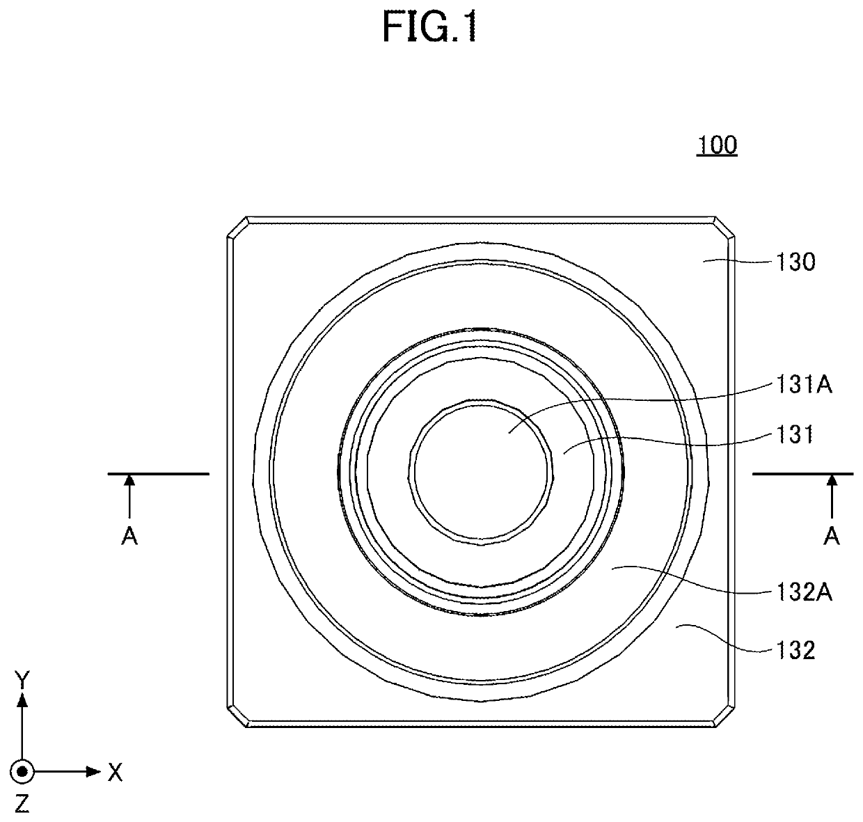
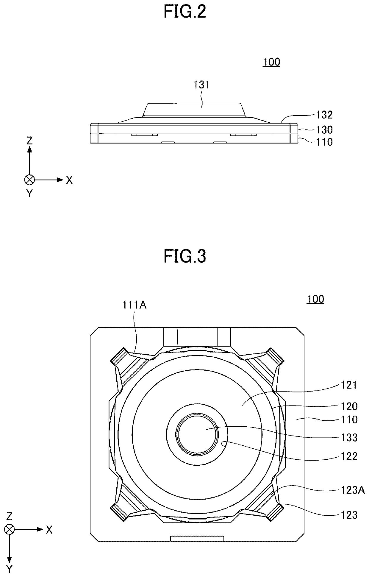
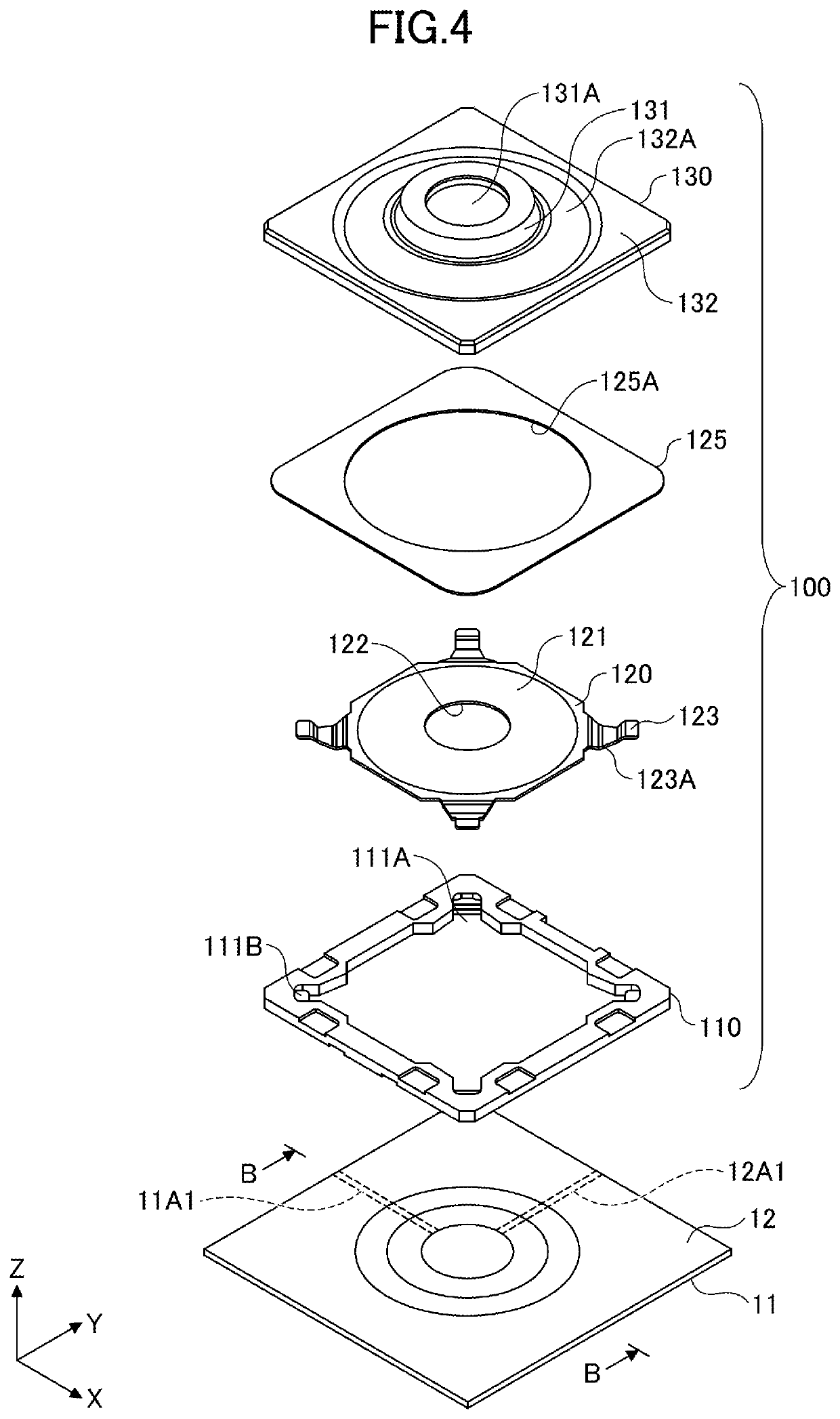
[0022]FIG. 1 is a plan view illustrating a pressing mechanism 100 of the push switch according to the first embodiment. FIG. 2 is a side view illustrating the pressing mechanism 100 of the push switch according to the first embodiment. FIG. 3 is a bottom view illustrating the pressing mechanism 100 of the push switch according to the first embodiment. FIG. 4 is an exploded view illustrating the pressing mechanism 100 of the push switch. FIG. 5 is a cross-sectional view taken along A-A of FIG. 1. FIG. 6 is a cross-sectional view of a membrane switch 10.

[0023]In FIG. 5, for example, a key top 20 of a keyboard is shown above the pressing mechanism 100 of the push switch. The pressing mechanism 100 of the push switch can be used as, for example, a pressing mechanism for each key top 20 of the keyboard. A guide member in a pantograph structure may be provided between the pressing mechanism 100 of the push switch and the key top 20. However, the purpose of the pressing mec...

Example

Second Embodiment

[0076]FIG. 10 is a drawing illustrating a push switch 200 according to the second embodiment. FIG. 11 is an exploded view illustrating the push switch 200. In the second embodiment, elements that are substantially the same as those of the first embodiment are denoted with the same reference numerals, and description thereabout is omitted.

[0077]The push switch 200 includes a housing 210, a leaf spring 250, a leaf spring 220, a thermocompression bonding sheet 125, and a stem 130. Hereinafter, FIG. 5 is incorporated herein by reference as an explanation about the stem 130. The push switch 200 may include the stem 130M as illustrated in FIG. 9 instead of the stem 130.

[0078]The housing 210 is made of resin, and is a plate-shaped member (housing) that has the same length in the X axis direction and the Y axis direction and that has a thickness in the Z axis direction. The housing 210 is different from the housing 110 of the first embodiment in that the accommodation porti...

Example

Third Embodiment

[0096]FIG. 12 is a drawing illustrating the pressing mechanism 300 of the push switch according to the third embodiment. FIG. 13 is an exploded view illustrating the pressing mechanism 300 of the push switch. In the third embodiment, elements that are substantially the same as those of the first embodiment are denoted with the same reference numerals, and description thereabout is omitted.

[0097]The pressing mechanism 300 of the push switch includes a housing 110, a leaf spring 120, a thermocompression bonding sheet 125, and a stem 130. Hereinafter, FIG. 5 is incorporated herein by reference as an explanation about the stem 130. The pressing mechanism 300 of the push switch may include the stem 130M as illustrated in FIG. 9 instead of the stem 130.

[0098]The pressing mechanism 300 of the push switch is implemented on a substrate 50. The pressing mechanism 300 of the push switch and the substrate 50 constitute the push switch.

[0099]The substrate 50 is a conductive trace...


PUM


Abstract

A pressing mechanism of a push switch including an operation member configured to be pressed, and a leaf spring member that includes a dome portion bulging in a dome shape and an opening portion provided in a central portion of the dome portion, the leaf spring member generating a tactile sensation on the operation member by an inverting operation of the dome portion in response to being pressed by the operation member, wherein the operation member includes a first pressing portion configured to press a movable contact point member against a fixed contact point member through the opening portion and a second pressing portion configured to press the dome portion.

Description

CROSS-REFERENCE TO RELATED APPLICATION[0001]The present application is a continuation application filed under 35 U.S.C. 111 (a) claiming benefit under 35 U.S.C. 120 and 365 (c) of PCT International Application No. PCT / JP2020 / 043094 filed on Nov. 18, 2020 and designating the U.S., which claims priority to Japanese Patent Application No. 2019-222452 filed on Dec. 9, 2019. The entire contents of the foregoing applications are incorporated herein by reference.BACKGROUND OF THE INVENTION1. Field of the Invention[0002]The present disclosure relates to a pressing mechanism of a push switch and relates to the push switch.2. Description of the Related Art[0003]For example, Japanese Laid-Open Patent Publication No. 2011-060601 discloses a key switch device that includes a switch panel having an opening at the center thereof; a key top positioned over the switch panel; a pair of link members positioned between the key top and the switch panel and adapted to support the key top so that the key ...

Claims


Application Information

Patent Timeline
IPC IPC(8): H01H13/14H01H13/20
CPCH01H13/14H01H13/20H01H13/48H01H2215/036H01H2227/002H01H2227/022
Inventor SATO, HIDETAKAMAKINO, SHINYAHANAWA, NAOKI
Owner ALPS ALPINE CO LTD
Why Eureka
Try Eureka