Pressure jackets and syringe retention features for angiography fluid injectors

Pending Publication Date: 2022-10-06
BAYER HEALTHCARE LLC
View PDF0 Cites 0 Cited by
  • Summary
  • Abstract
  • Description
  • Claims
  • Application Information

AI Technical Summary

Benefits of technology

The patent describes a system for retaining a syringe and pressure jacket in a medical injector during injection. The system includes a base plate with two retaining arms that hold the syringe and pressure jacket in place. The retaining arms move between an open position and a closed position. The system also includes a linkage assembly that connects to the retaining arms and can move them between the open and closed positions. The technical effect of this system is to securely hold the syringe and pressure jacket in place during injection, making the injection process easier and safer.

Problems solved by technology

During certain injection procedures, the syringe itself may not be capable of withstanding the high pressure without excessive radial expansion of the syringe wall under such pressure.
This may result in undesired changes in fluid delivery volumes and flow rates or potentially even structural failure.

Method used


Image

  • Pressure jackets and syringe retention features for angiography fluid injectors
  • Pressure jackets and syringe retention features for angiography fluid injectors
  • Pressure jackets and syringe retention features for angiography fluid injectors

Examples


Embodiment Construction

[0089]As used herein, the singular form of “a”, “an”, and “the” include plural referents unless the context clearly dictates otherwise.

[0090]Spatial or directional terms, such as “left”, “right”, “inner”, “outer”, “above”, “below”, and the like, relate to the invention as shown in the drawing figures and are not to be considered as limiting as the invention can assume various alternative orientations.

[0091]All numbers used in the specification and claims are to be understood as being modified in all instances by the term “about”. The term “about” is meant to include plus or minus twenty-five percent of the stated value, such as plus or minus ten percent of the stated value. However, this should not be considered as limiting to any analysis of the values under the doctrine of equivalents.

[0092]Unless otherwise indicated, all ranges or ratios disclosed herein are to be understood to encompass the beginning and ending values and any and all subranges or sub-ratios subsumed therein. For...


PUM


Abstract

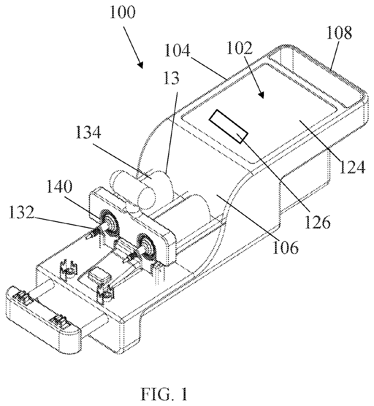
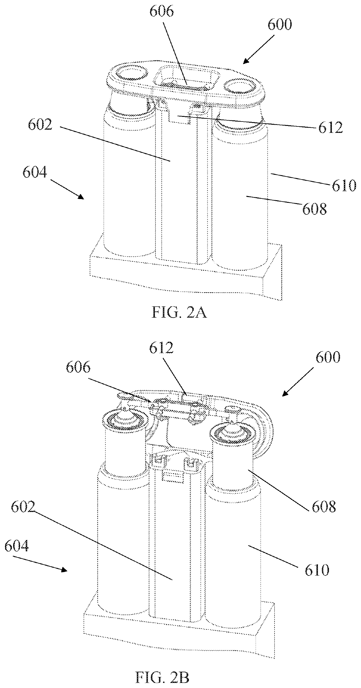
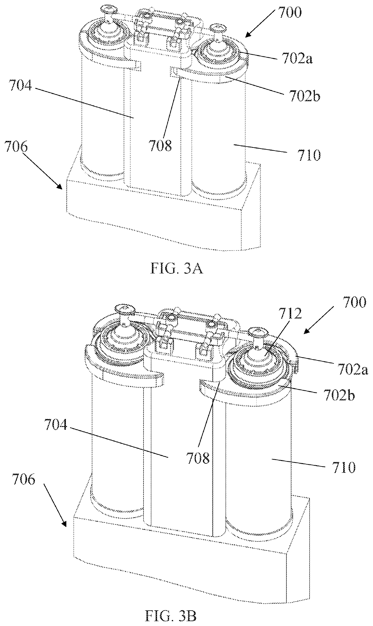
An assembly for retaining a pressure jacket (134) and a syringe (132) on a fluid injector, the assembly including a base plate (1902) comprising a body (1904); at least a first retaining arm (1910a) and a second retaining arm (1910b) operatively mounted on the body of the base plate, the first retaining arm having a first retaining surface at a distal end thereof and the second retaining arm having a second retaining surface at a distal end thereof, wherein the first retaining surface and the second retaining surface are configured for abutting a distal surface of at least one of the pressure jacket and the syringe; a linkage assembly operatively connected to at least one of the first retaining arm and the second retaining arm, wherein the linkage assembly is configured to move at least one of the first retaining arm and the second retaining arm between at least a first open position and a closed position.

Description

CROSS REFERENCE TO RELATED APPLICATION[0001]The present application claims the benefit of U.S. Provisional Patent Application No. 62 / 898,289, filed on 10 Sep. 2019, and U.S. Provisional Patent Application No. 62 / 979,048, filed 20 Feb. 2020, the disclosures of which are incorporated in their entireties by reference.BACKGROUND OF THE DISCLOSUREField of the Disclosure[0002]The present disclosure relates generally to angiography fluid injectors having the one or more syringe retention features configured for retaining a syringe and a pressure jacket, wherein the syringe retention features engage a distal end of the syringe and the pressure jacket to limit movement of the syringe in a distal direction during a fluid injection procedure and support the distal end of the syringe under pressure.Description of Related Art[0003]In many medical diagnostic and therapeutic procedures, a medical practitioner injects a patient with one or more medical fluids. In recent years, a number of injector-...

Claims


Application Information

Patent Timeline
IPC IPC(8): A61M5/00
CPCA61M5/007A61M2209/082A61M2205/586A61M5/14546A61M5/20A61M5/14566
Inventor SPOHN, MICHAELCOWAN, KEVINUBER, III, ARTHURCAMPBELL, PATRICKOSAN, ANDREWHAURY, JOHNDEDIG, JAMESNAPLES, ANDREWSCUTT, CHRISTOPHERSWANTNER, MICHAELPAYOR, NATHANIEL
Owner BAYER HEALTHCARE LLC
Why Eureka
Try Eureka