Eureka AIR delivers breakthrough ideas for toughest innovation challenges, trusted by R&D personnel around the world.

Air chuck

Pending Publication Date: 2022-10-06
SMC CORP
View PDF0 Cites 0 Cited by
  • Summary
  • Abstract
  • Description
  • Claims
  • Application Information

AI Technical Summary

Benefits of technology

The present invention allows for easy attachment and detachment of a chuck unit from an operation unit by locking the pair of fingers in fixed positions. This eliminates the need for adjusting the positions of the fingers and provides a more efficient mechanism for automatically replacing the chuck unit using a robot or the like.

Problems solved by technology

In a commonly known air chuck, however, when the chuck unit is detached from the operation unit, the pair of fingers are brought into a free state, and thus, the pair of fingers are freely displaced, so that a fixed positional relationship cannot be maintained.

Method used


Image

  • Air chuck
  • Air chuck
  • Air chuck

Examples


Embodiment Construction

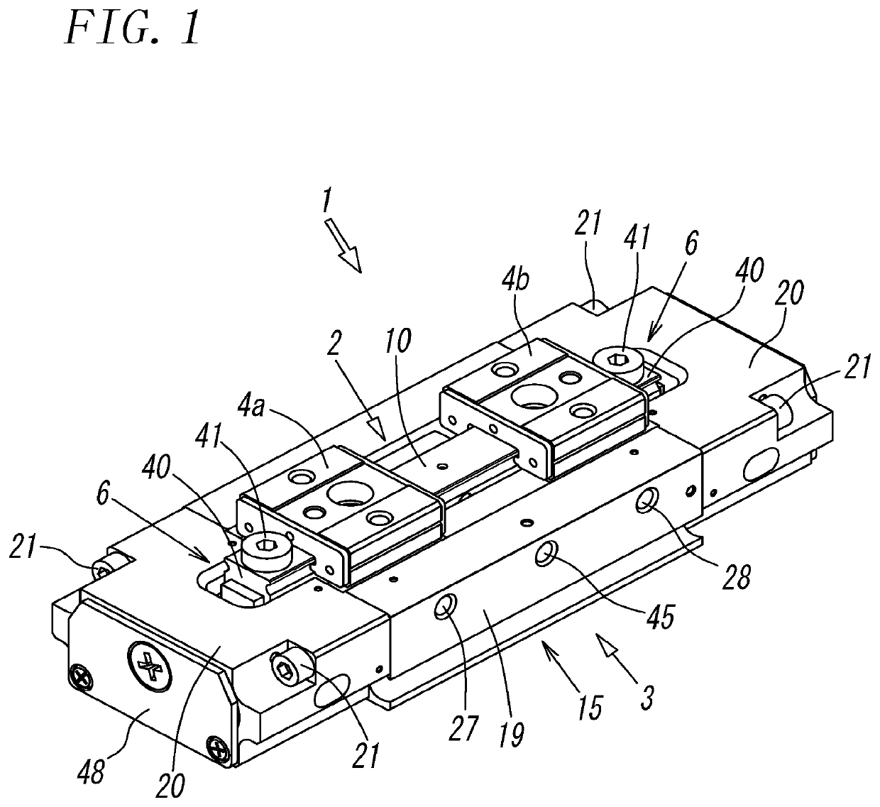
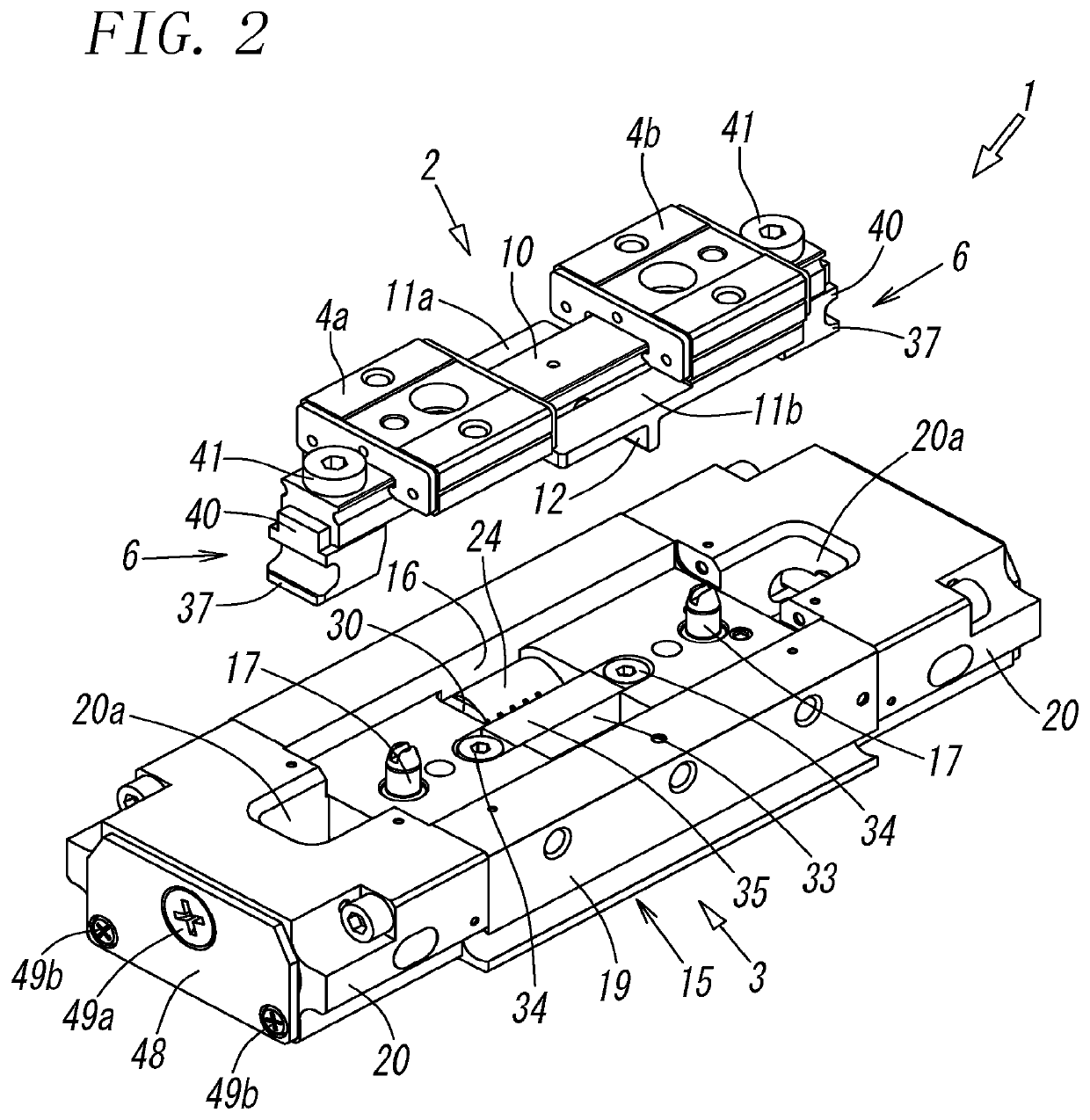
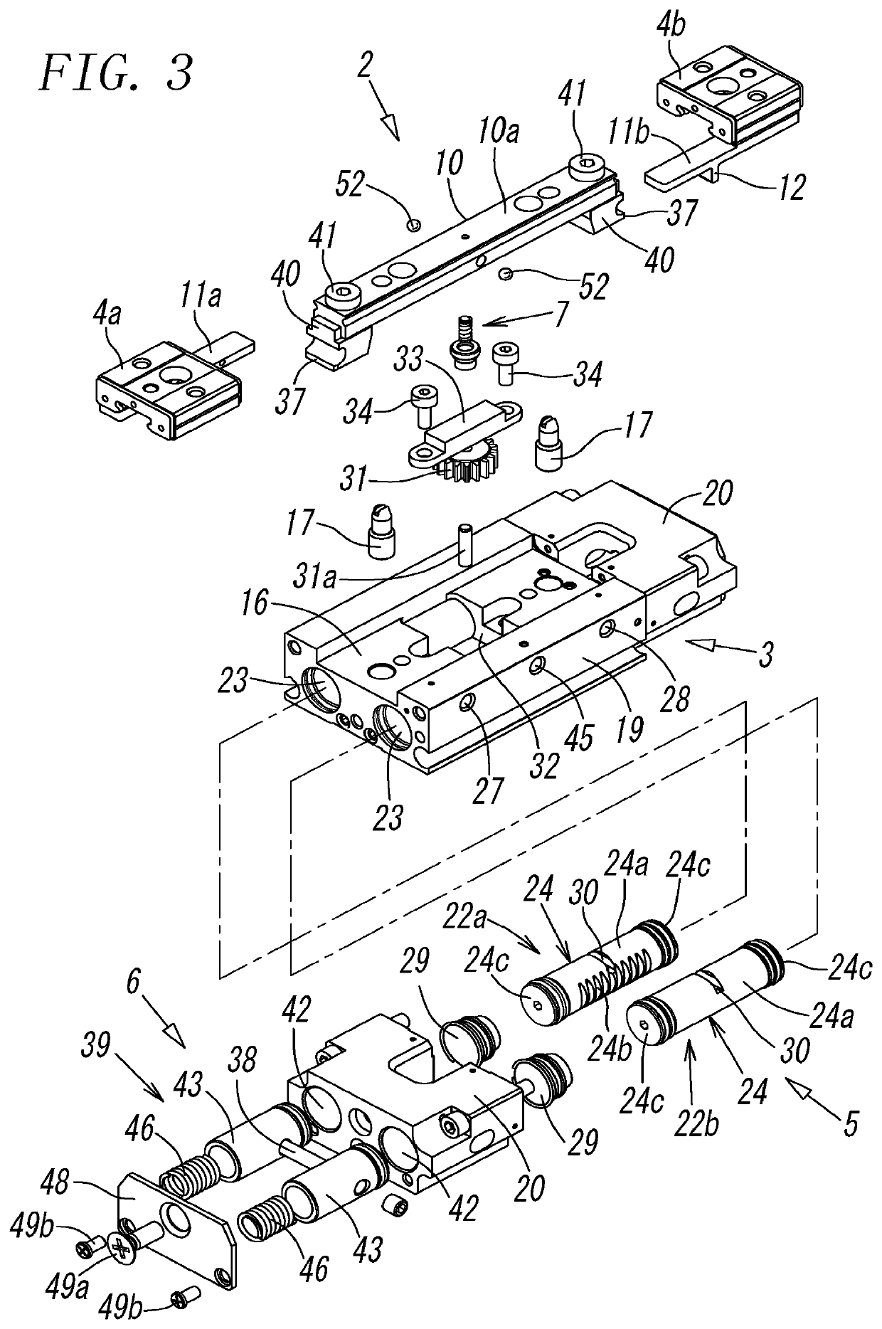
[0032]FIG. 1 to FIG. 11 illustrate an air chuck according to the first embodiment of the present invention. An air chuck 1 includes a chuck unit 2 including a pair of fingers 4a and 4b that are capable of being freely opened and closed so as to chuck a workpiece, an operation unit 3 including an operation mechanism 5 that opens and closes the pair of fingers 4a and 4b, connection mechanisms 6 and 6 that connect the chuck unit 2 and the operating unit 3 to each other such that the chuck unit 2 is freely attachable and detachable to and from the operating unit 3, and a locking mechanism 7 that locks the pair of fingers 4a and 4b such that the pair of fingers 4a and 4b are not able to be opened or closed when the chuck unit 2 is detached from the operation unit 3.

[0033]As illustrated in FIG. 1 to FIG. 5, the chuck unit 2 includes a linearly elongated bar-shaped support member 10, and the top surface of the support member 10 serves as a rail portion 10a. The pair of fingers 4a and 4b st...


PUM


Abstract

An air chuck includes a chuck unit including a pair of fingers that capable of being freely opened and closed, an operation unit that includes an operation mechanism, which opens and closes the pair of fingers, connection mechanisms for attaching the chuck unit to the operation unit such that the chuck unit is freely attachable and detachable to and from the operating unit, and a locking mechanism that locks the pair of fingers such that the pair of fingers are capable of being freely opened and closed when the chuck unit is attached to the operation unit and such that the pair of fingers are not able to be opened or closed when the chuck unit is detached from the operation unit.

Description

TECHNICAL FIELD[0001]The present invention relates to an air chuck including a pair of fingers that are capable of being freely opened and closed, and more particularly to an air chuck in which a chuck unit that includes the pair of fingers is freely attachable and detachable to and from an operation unit that opens and closes the fingers.BACKGROUND ART[0002]An air chuck in which a chuck unit including a pair of fingers that are capable of being freely opened and closed and an operation unit including an operation mechanism that opens and closes the pair of fingers are freely attachable and detachable to and from each other is commonly known as disclosed in, for example, Patent Literatures PTL 1 to PTL 3. This type of air chuck can handle a wide variety of workpieces by replacing the chuck unit in accordance with the type of a workpiece and thus is efficient and economical.[0003]In a commonly known air chuck, however, when the chuck unit is detached from the operation unit, the pair...

Claims


Application Information

Patent Timeline
IPC IPC(8): B25J15/08
CPCB25J15/083B25J15/00B25J15/02B25J15/08B25J15/0253B25J15/086B25J15/04B23B2270/027B23B31/16066
Inventor KANDA, KOUICHIROUHARA, KOJISASAKI, TSUYOSHI
Owner SMC CORP
Why Eureka
Eureka Blog
Learn More