Dual-band integrated printed antenna feed
a printed antenna and integrated technology, applied in the direction of antennas, waveguides, waveguide horns, etc., can solve the problems of high variability of antenna performance between units, long fabrication and test times, and significant labor and manufacturing costs
- Summary
- Abstract
- Description
- Claims
- Application Information
AI Technical Summary
Benefits of technology
Problems solved by technology
Method used
Image

Examples
first embodiment
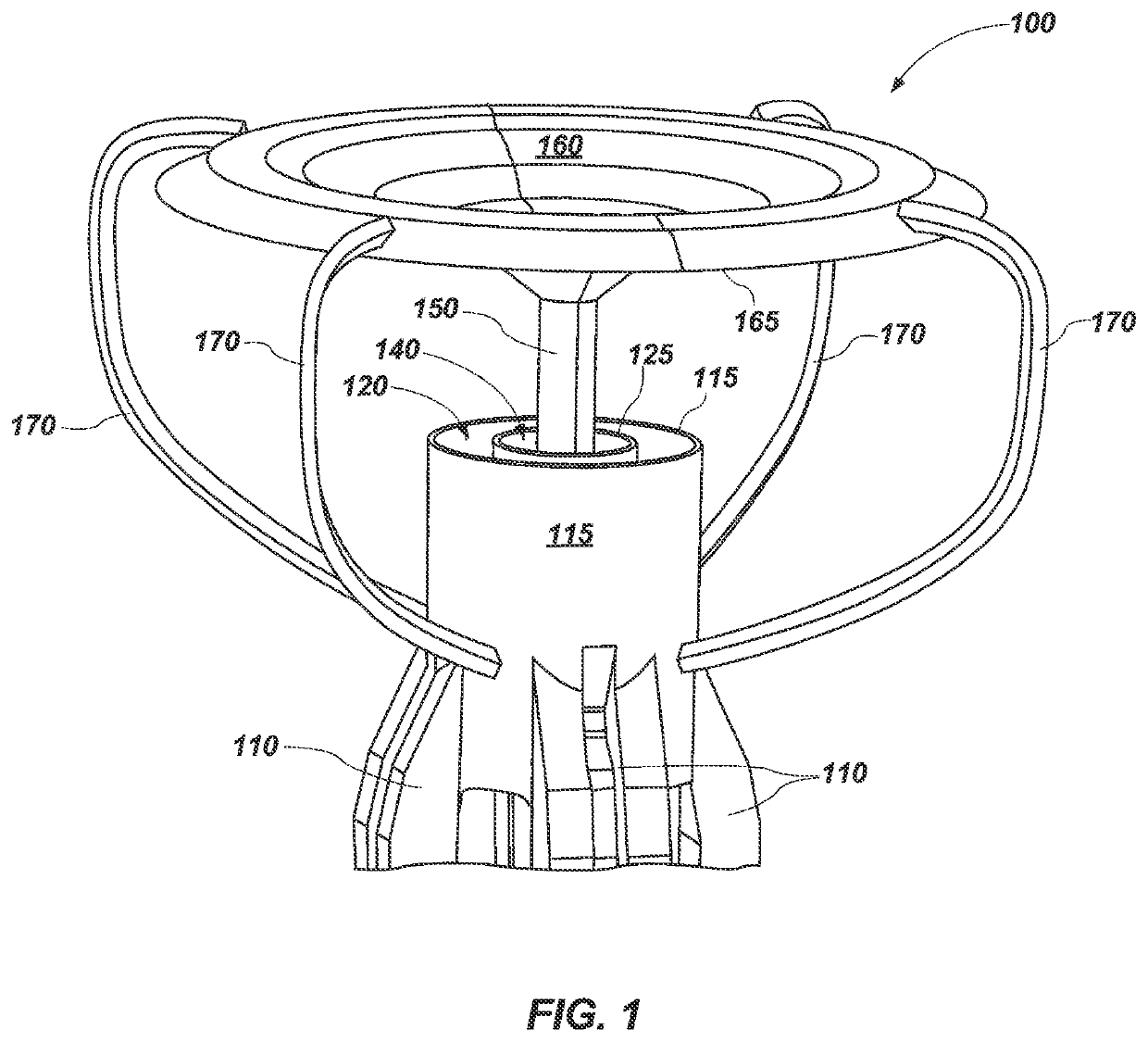
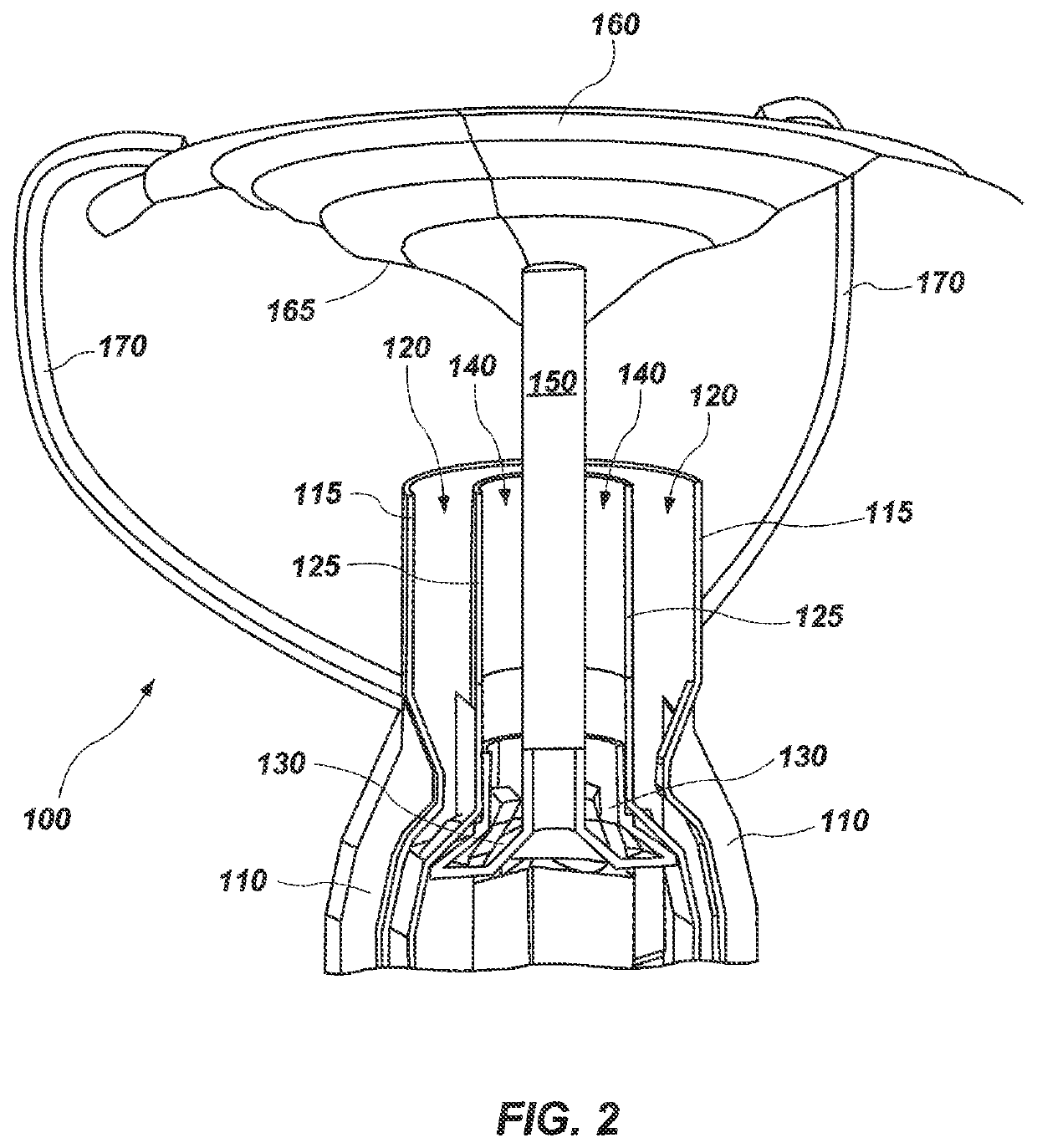
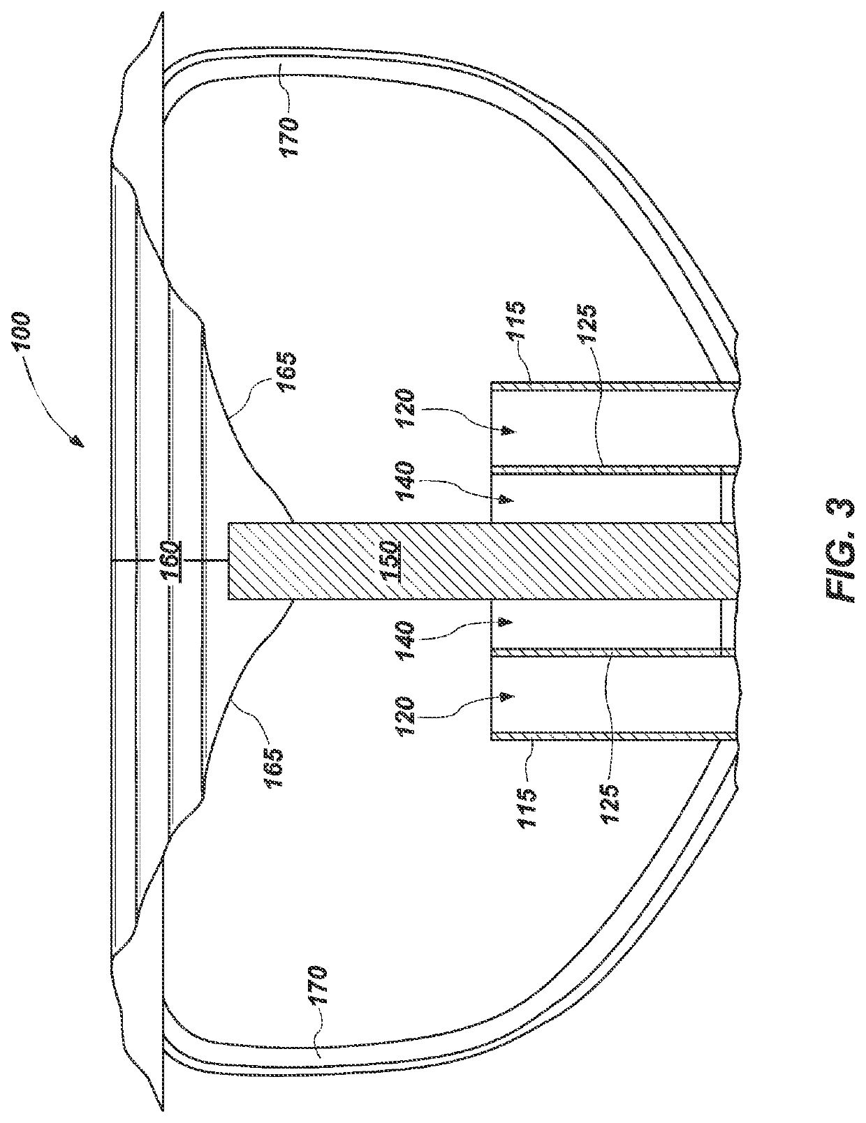
[0043]FIG. 1 is a partial perspective view of a dual-band integrated printed antenna (DIPA) 100, according to the present invention. DIPA 100 may include a lower frequency coaxial turnstile 110 transitioning to an outer coaxial cylinder 115. DIPA 100 may further include an inner coaxial cylinder 125. DIPA 100 may further include a lower frequency outer coaxial horn 120 located in between the inner 125 and outer 115 coaxial cylinders. DIPA 100 may further include a higher frequency inner coaxial turnstile 130 (not shown in FIG. 1, but located inside lower frequency coaxial turnstile 110). DIPA 100 may further include a higher frequency inner coaxial horn 140 surrounding a coaxial subreflector support 150. The coaxial subreflector support 150 physically supports subreflector 160. Subreflector 160 may also be physically supported by strut subreflector supports 170. Although four strut subreflector supports 170 are shown in FIG. 1, it will be understood that any suitable number, e.g., o...
fourth embodiment
[0056]In operation of a DIPA 400, a lower frequency electromagnetic wave, or signal, may emanate from the lower frequency coaxial horn 420 and be reflected off of the bottom surface 465 of subreflector 460 to illuminate a main reflector (not shown) of larger diameter which bounces the wave a toward its intended location, typically another antenna (not shown) located some distance away, e.g., from satellite to earth or vice versa. Alternatively as noted above, a lower frequency electromagnetic wave may travel in the opposite direction, first reflecting off of the bottom surface 465 of subreflector 460 before entering into the lower frequency coaxial horn 420 for further signal processing via lower frequency coaxial turnstile 410.
[0057]FIG. 7 is a full side-view of a fifth embodiment of a DIPA 500, according to the present invention. The fifth embodiment of a DIPA 500 may include a lower frequency coaxial input 595 feeding a lower frequency input coaxial turnstile 580, which in turn f...
fifth embodiment
[0058]a DIPA 500 may further include a higher frequency circular waveguide input 590 (not visible in FIG. 7, but located inside the lower frequency coaxial input 595 at bottom of FIG. 7), which feeds a higher frequency input circular waveguide turnstile 585 (partially obstructed by the center lower frequency polarizer phase shifting arm 575), which in turn feeds higher frequency polarizer phase shifting arms 565 (two of four shown, the other two arms 565 hidden behind), which in turn feeds a higher frequency inner coaxial turnstile 530 (not visible in FIG. 7, but, embedded within the lower frequency output coaxial turnstile 510 and polarizer arms 565, 575), and finally which feeds a higher frequency inner coaxial horn (not visible, but see arrows 540), The higher frequency inner coaxial horn 540 is located inside lower frequency outer coaxial horn 520).
[0059]The fifth embodiment of a DIPA 500 may further include a subreflector 560, a coaxial subreflector support 550 and strut subref...
PUM
 Abstract
Description
Claims
Application Information
 - R&D
- Intellectual Property
- Life Sciences
- Materials
- Tech Scout
- Unparalleled Data Quality
- Higher Quality Content
- 60% Fewer Hallucinations
Browse by: Latest US Patents, China's latest patents, Technical Efficacy Thesaurus, Application Domain, Technology Topic, Popular Technical Reports.
© 2025 PatSnap. All rights reserved.Legal|Privacy policy|Modern Slavery Act Transparency Statement|Sitemap|About US| Contact US: help@patsnap.com