Treatment device for eye surgery

a treatment device and eye surgery technology, applied in the field of eye surgery, can solve the problems of induced visual defect, different treatment apparatuses to be used, no longer used,

Pending Publication Date: 2022-10-13
CARL ZEISS MEDITEC AG
View PDF0 Cites 0 Cited by
  • Summary
  • Abstract
  • Description
  • Claims
  • Application Information

AI Technical Summary

Benefits of technology

[0024]Embodiments of the invention specify a planning device for generating control data, a treatment apparatus for refraction-correcting eye surgery, and a method for generating control data for such a treatment apparatus, which facilitate an improved correction of the refraction.
[0025]According to the invention, this object is achieved by a planning device of the type set forth at the outset, the latter comprising a calculation application for defining the corneal cut surfaces, which, during the determination of the cut surfaces, facilitates a rotation of the cut surface about an axis running substantially parallel to the ocular axis.
[0026]Thus, the physician can carry out an optimal placement of the cuts in the cornea according to their experience, in particular compensate a rotation of the eye of the patient when adopting the treatment position.

Problems solved by technology

However, a disadvantage of this method is that two different treatment apparatuses have to be used, specifically firstly the laser keratome for exposing the lamella and, secondly, the laser that vaporizes the corneal tissue.
Secondly, this only still requires one treatment apparatus; the excimer laser is no longer used.
What is common to all these known methods is that the success of the treatment depends on the reliable assignment of the intended cut or intended cuts to the geometry of the eye to be treated since even small deviations from the envisaged refraction correction may lead to a non-optimal correction and hence to an induced visual defect.
This method is inaccurate and provides no quantitative feedback to the physician about the angle of rotation that has been adapted by them.
This may lead to an elevated suction loss risk (loss of suction of the contact glass on the eye) and is perceived as uncomfortable by the patient.

Method used


Image

  • Treatment device for eye surgery
  • Treatment device for eye surgery
  • Treatment device for eye surgery

Examples


Embodiment Construction

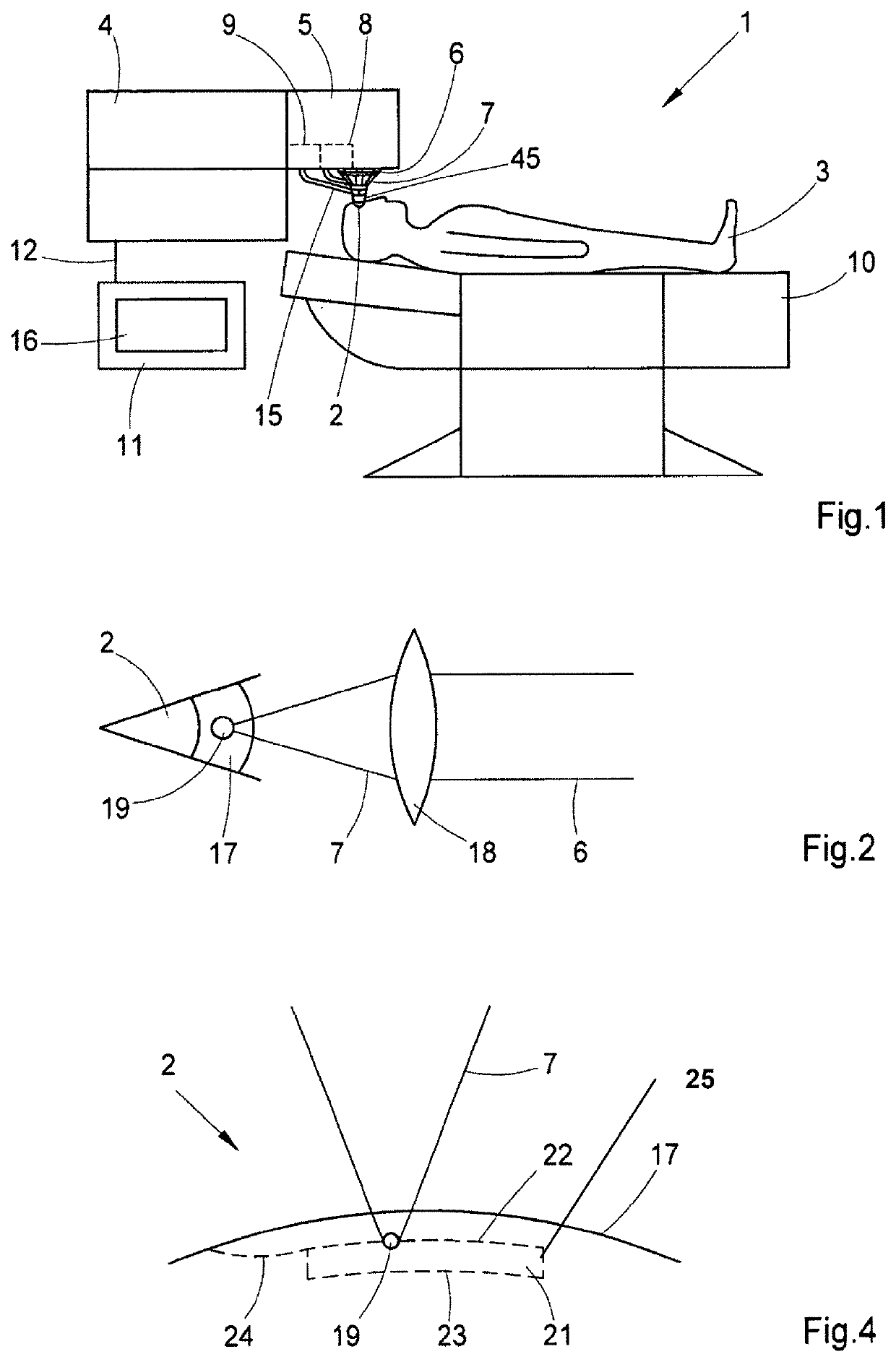
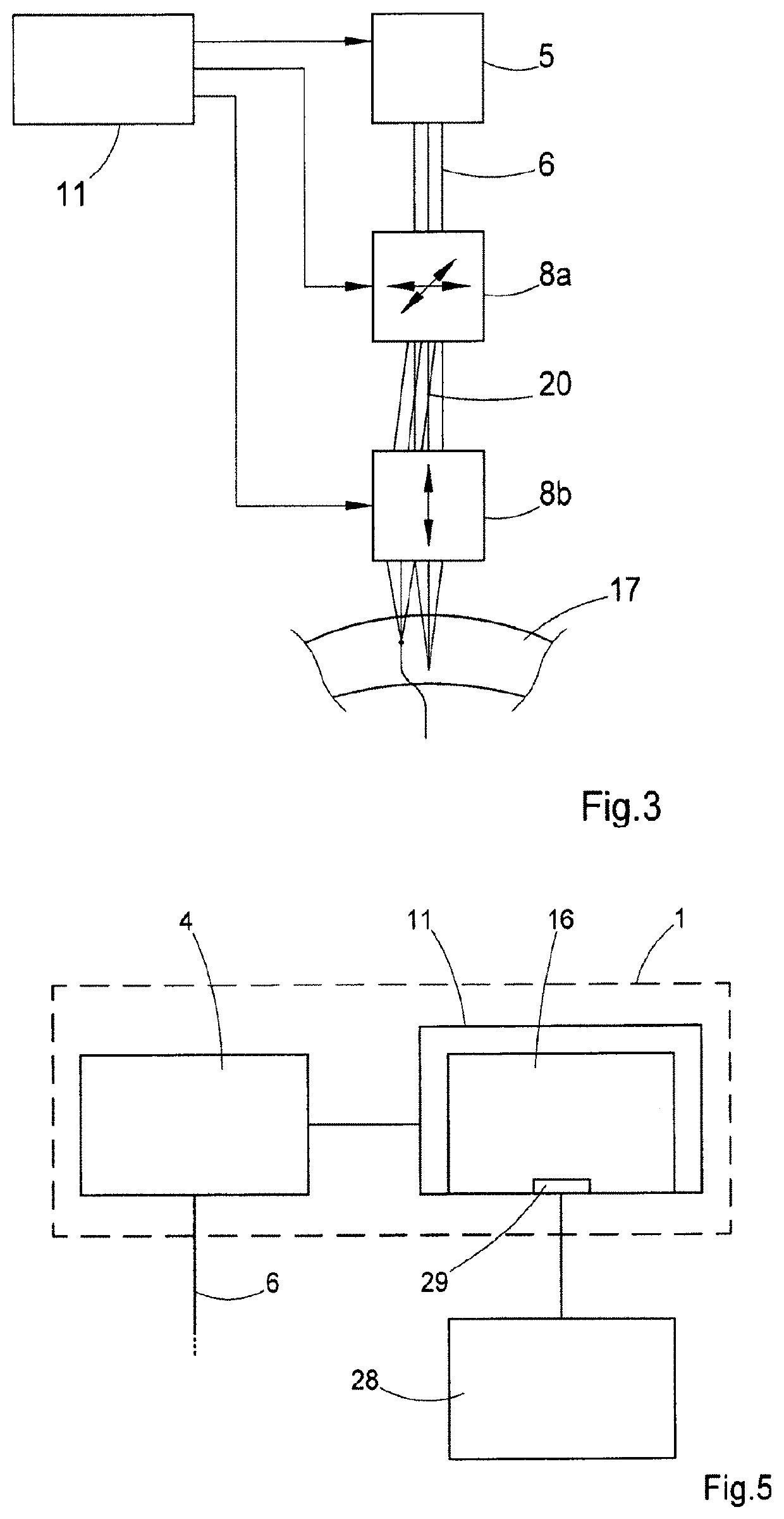
[0071]A treatment apparatus for eye surgery is illustrated in the FIG. 1 and provided with the general reference sign 1. The treatment apparatus 1 is designed to introduce laser cuts on an eye 2 of a patient 3. To this end, the treatment apparatus 1 comprises a laser device 4 which emits a laser beam 6 from a laser source 5, the laser beam being directed into the eye 2 or the cornea of the eye as a focused beam 7. For example, the laser beam 6 is a pulsed laser beam with a wavelength between 300 nanometers and 10 micrometers. Further, the pulse length of the laser beam 6 is in the range between 1 femtosecond and 100 nanoseconds, with pulse repetition rates of 500 kilohertz and 30 MHz, for example 1.2 to 10 MHz, and pulse energies between 1 nanojoule and 10 microjoules, for example 1 to 200 nanojoules being possible. The treatment apparatus 1 therefore generates a cut surface in the cornea of the eye 2 by deflecting the pulsed laser radiation. Therefore, a scanner 8 and a radiation i...


PUM


Abstract

A planning device that generates control data for a treatment apparatus which produces at least one cut surface in the cornea by application of a laser device. The invention further relates to a treatment apparatus having a planning device of the aforementioned type and a method for generating control data for this treatment apparatus, and also to a method for eye surgery, at least one cut surface being produced by application of a treatment apparatus with a laser device. The planning device includes a calculation application that defined corneal cut surfaces, which facilitates a largely free assignment to geometric variables of the eye. The method for generating control data includes generating a control data record for the corneal cut surface that controls the laser device, wherein the planning device, during the determination of the cut surfaces, facilitates a largely free assignment to geometric variables of the eye.

Description

RELATED APPLICATIONS[0001]This application is a National Phase entry of PCT Application No. PCT / EP2020 / 075059 filed Sep. 8, 2020, which application claims the benefit of priority to DE Application No. 10 2019 213 735.0 filed Sep. 10, 2019, the entire disclosures of which are incorporated herein by reference.TECHNICAL FIELD[0002]The invention relates to a planning device for generating control data for a treatment apparatus which produces at least one cut surface in the cornea by application of a laser device. The invention further relates to a treatment apparatus having a planning device of the aforementioned type.[0003]The invention also relates to a method for generating control data for a treatment apparatus which produces at least one cut surface in the cornea by application of a laser device.[0004]The invention finally likewise relates to a method for eye surgery, at least one cut surface being produced in the cornea by application of a treatment apparatus with a laser device.[...

Claims


Application Information

Patent Timeline
Patent Type & Authority Applications(United States)
IPC IPC(8): A61F9/008
CPCA61F9/00804A61F2009/00878A61F2009/00872A61F9/00825
Inventor BRÜCKNER, FRANKLEHNORT, MARCOWEYHAUSEN, ANDREASSTOBRAWA, GREGOR
Owner CARL ZEISS MEDITEC AG
Why Eureka
Try Eureka