Running bended exerciser

Pending Publication Date: 2022-10-13
CAPUTI GIANCARLO
View PDF0 Cites 0 Cited by
  • Summary
  • Abstract
  • Description
  • Claims
  • Application Information

AI Technical Summary

Benefits of technology

[0006]Therefore said supports (2,2′) can be rotated in an open position (when used) generating an angle-space in which a user can place himself (FIG. 1, three-dimensional view; FIG. 2, view from above), or in a folded close position (when not used) (FIG. 3, view from above). Each of said supports (2,2′) can adjust the height of upper horizontal member (22,22′), usable as a handle-bar (22,22′), to which a user c

Problems solved by technology

Therefore the user runs in straight position, which increases compressio

Method used


Image

  • Running bended exerciser
  • Running bended exerciser

Examples


Example

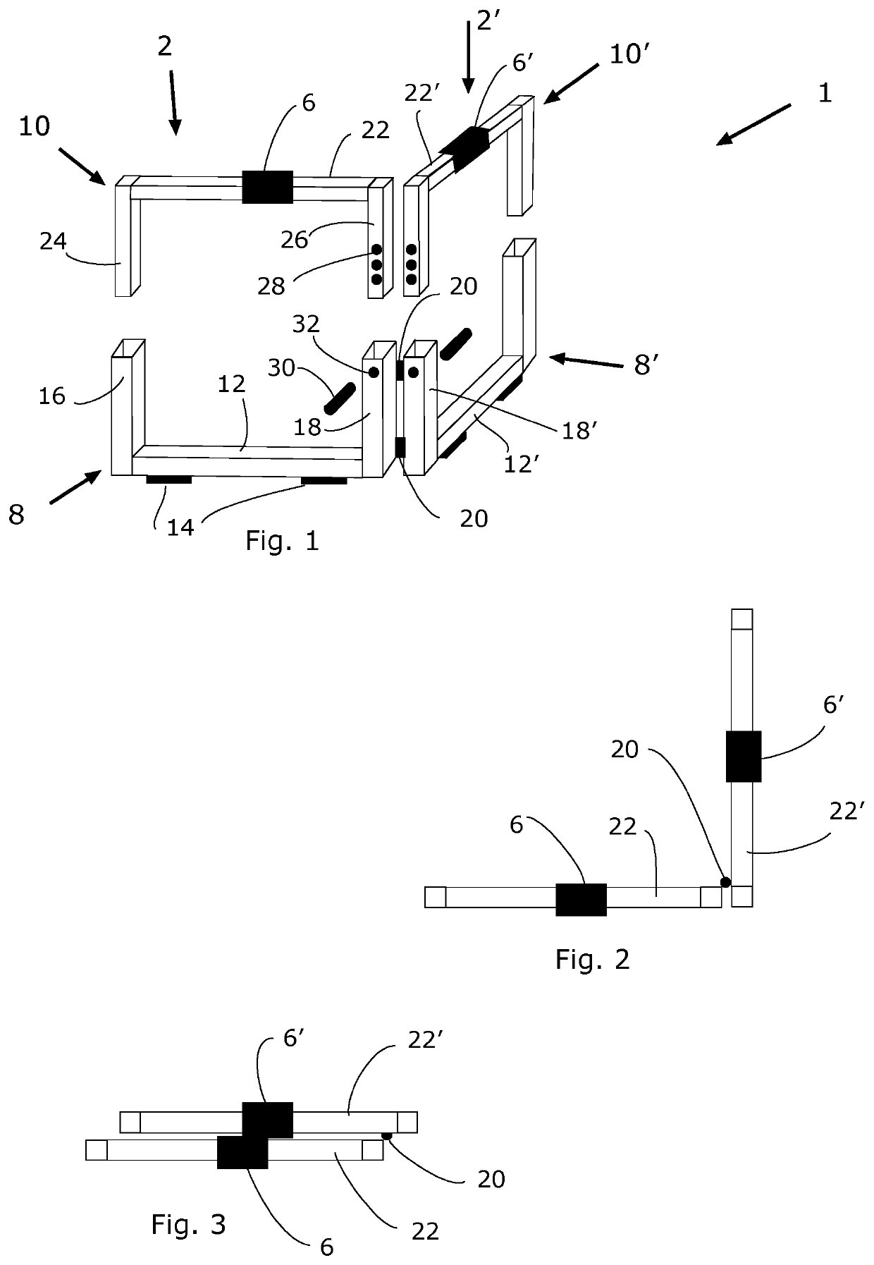
[0014]Whereby each of said identical rectangle-shaped supports (2,2′) is composed by two parts which fit together. With reference to first support (2) it comprises:

[0015]a) a U shaped lower part (8)

[0016]b) An upside down U shaped upper part (10)

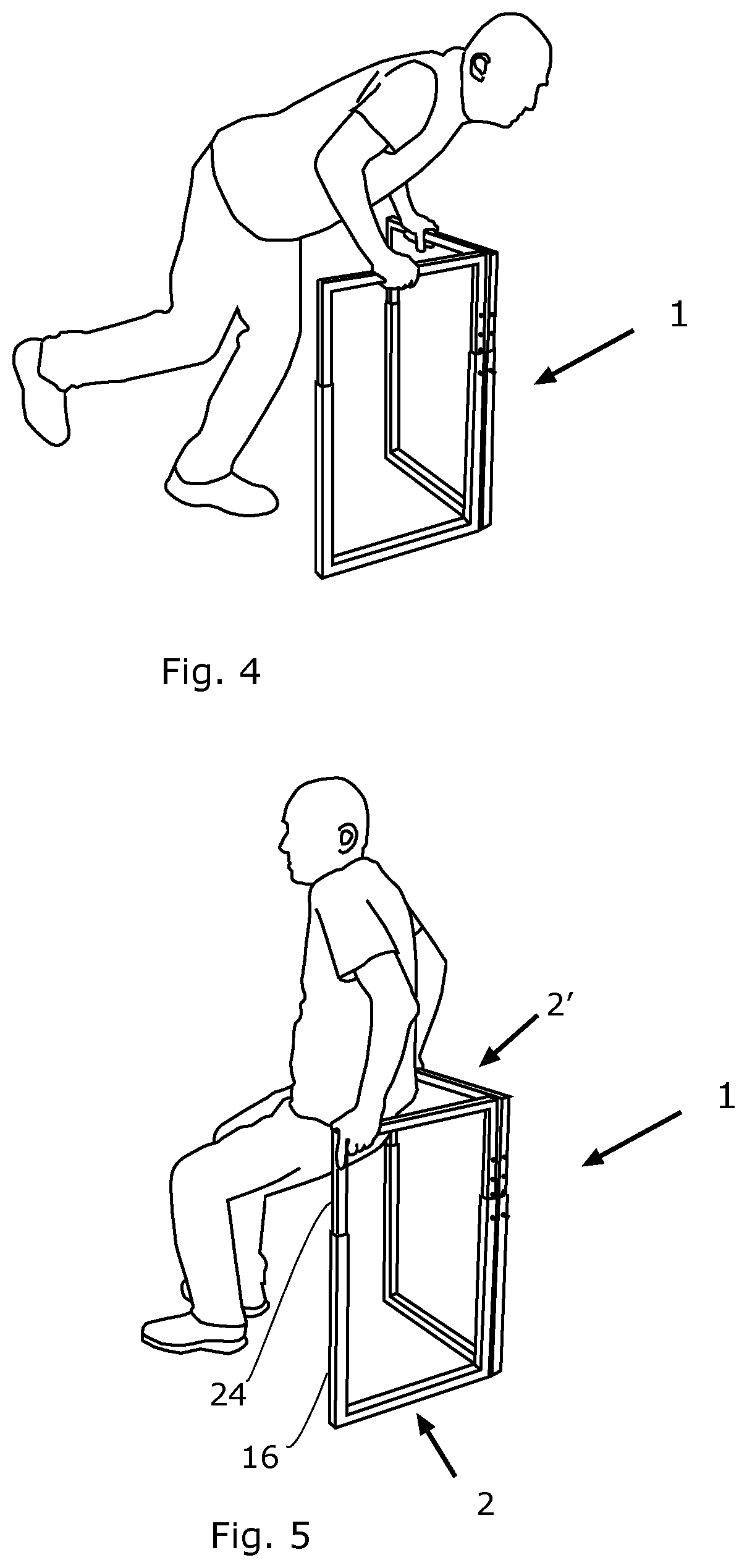
[0017]Said U shaped lower part (8) comprises a lower horizontal member (12) and two vertical tubular female elements (16,18), upwards directed. Said lower horizontal member (12) rests on the floor. Said vertical tubular elements (16,18) work as female sliding joints for the housing of vertical lateral male elements (24,26) (disclosed below).

[0018]One (18) of vertical tubular elements has hinges (20) for connection with corresponding element (18′) of second support (2′).

[0019]Said upside down U shaped upper part (10) comprises an upper horizontal member (22) usable as a handle-bar and two vertical lateral male elements (24,26), downwards directed.

[0020]Said upper horizontal member (22) has a soft handle (6) sliding on said member (22) and is ...


PUM


Abstract

Exerciser (1) which allows to perform two new exercises: 1) Leaning miming in place exercise (FIGS. 4) and 2) Traction in suspension exercise (FIG. 5). Two identical rectangle-shaped supports (2, 2′), hinged on two adjacent vertical sides (18, 18) permit a user to grip upper horizontal handle-bars (22, 22). When not in use, the exerciser (1) can be folded, occupying a very small space (FIG. 3).

Description

TECHNICAL FIELD[0001]The invention relates to training equipments.BACKGROUND ART[0002]Running in place exercisers are generally meant to permit a user to run at home while a machine activates a tapis-roulant. Therefore the user runs in straight position, which increases compression of his back. Moreover, these machines are heavy and bulky and expensive. Actually there are no tools for running leaning and bended, which is an exercise of my invention (FIG. 4). With regards to traction in suspension exercise (FIG. 5), it can be practiced with the parallel bars for artistic gymnastics, a very heavy and bulky exerciser.DISCLOSURE OF INVENTION[0003]The invention relates to an exerciser (1) comprising two identical rectangle-shaped support elements, or supports (2,2′), hinged on two adjacent vertical sides (18,18′). Each support has an upper horizontal member (22,22′) usable as a handle-bar (22,22′), a lower horizontal member (12,12′) meant as support base, a first lateral member, a second...

Claims


Application Information

Patent Timeline
IPC IPC(8): A63B21/00
CPCA63B21/00047A63B21/4035A63B2210/50A63B2225/093A63B2208/0204A63B21/068A63B23/1227A63B17/04A63B23/12A63B23/1209
Inventor CAPUTI, GIANCARLO
Owner CAPUTI GIANCARLO
Why Eureka
Try Eureka