Lighting system and artificial window

Pending Publication Date: 2022-10-27
SIGNIFY HLDG BV
View PDF8 Cites 1 Cited by
  • Summary
  • Abstract
  • Description
  • Claims
  • Application Information

AI Technical Summary

Problems solved by technology

However, this known artificial skylight device has the disadvantage that it

Method used


Image

  • Lighting system and artificial window
  • Lighting system and artificial window
  • Lighting system and artificial window

Examples


first embodiment

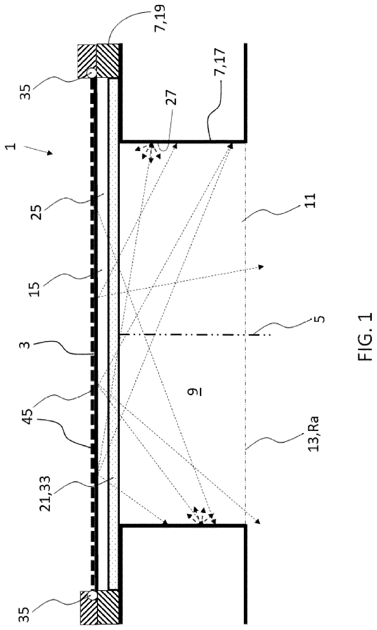
[0040]FIG. 1 shows an artificial window, for example an artificial skylight, of a lighting system 1 according to the invention. The lighting system comprises a light area 3 (also referred to as light generating area or light transmitting area) extending transverse to a main, axial direction 5, and a side wall 7 extending downstream from the light area, defining a recess 9 with a cross section Ra. The light area is located at a base 11 of the recess and a light exit window 13 is located downstream at a top 15 of the recess opposite the light area. The side wall comprises a first wall portion 17 and a second wall portion 19 located upstream of the first wall portion, and a transparent pane 21 is provided in between the first and second wall portion. The second wall portion is screened by the first wall portion from a direct line of view through the light exit window, in that the first wall portion is offset from the second wall portion in a radial direction into the recess. This is fu...

third embodiment

[0044]FIG. 4 shows an artificial window, for example a recessed wall portion, of a lighting system 1 according to the invention. The lighting system comprises a light area 3 extending transverse to a main, axial direction 5, and a side wall 7 extending downstream from the light area, defining a recess 9 with a cross section Ra. The light area is located at a base 11 of the recess and a light exit window 13 is located downstream at a top 15 of the recess opposite the light area. The side wall comprises a first wall portion 17 and a second wall portion 19 located upstream of the first wall portion, and a transparent pane 21 is provided in between the first and second wall portion. The second wall portion is screened by the first wall portion from a direct line of view through the light exit window, in that the first wall portion is offset from the second wall portion in a radial direction into the recess. The transparent pane, the light area and the second wall portion define a space ...


PUM


Abstract

The invention relates to a lighting system comprising a light area and a side wall around the light area defining a recess. The light area is located at a base of the recess and a light exit window is located downstream at a top of the recess opposite the light area. The side wall comprises a first wall portion and a second wall portion located upstream of the first wall portion. A clear, transparent pane is provided in between the first and second wall portion, wherein (essentially the whole of) the second wall portion is screened by the first wall portion from a direct line of view through the light exit window.

Description

FIELD OF THE INVENTION[0001]The invention relates to a lighting system and an artificial window.BACKGROUND OF THE INVENTION[0002]Artificial skylight devices are a relatively new class of devices drawing a lot of attention lately. Their aim is to provide human beings with a sense of being connected to nature whilst indoor where they may be fully or partially deprived from access to natural light. Examples of such indoor spaces are offices, corridors, subways, underground metro and train-stations, tunnels, hospitality areas, hospitals, planes, submarines, etc. etc. At present there exist many different artificial skylights ranging from (very) low-end, low-cost and static (backlit) posters to the more expensive, high-res dynamic TV and / or projector based devices towards the (almost) unpractical, unaffordable, huge size and weight, high-volumetric, high-tech devices, deploying wavelength-dependent nano-particle scattering, known as Rayleigh scattering (the reason for which the sky is bl...

Claims


Application Information

Patent Timeline
IPC IPC(8): F21S8/02F21V5/04F21V21/04H05B45/28F21S8/04
CPCF21S8/024F21V5/045F21V21/041H05B45/28F21S8/04F21Y2115/10F21V7/09F21V3/06F21V33/006F21V9/02F21Y2105/16
Inventor VAN DELDEN, MARTINUS HERMANUS WILHELMUS MARIA
Owner SIGNIFY HLDG BV
Why Eureka
Try Eureka