Electrically Active Hospital Bed Caddy with Adjustable Mobile Device Mount and Cable Harness

a technology of mobile device mount and cable harness, which is applied in the field of bed storage caddies, can solve the problems of affecting the operation, the entanglement of multiple electrical cords from the head wall, and the lack of organization and storage of many of the devices in the hospital room

Pending Publication Date: 2022-11-17
ARBOR DEVICES LLC
View PDF0 Cites 0 Cited by
  • Summary
  • Abstract
  • Description
  • Claims
  • Application Information

AI Technical Summary

Problems solved by technology

One of the difficulties experienced by patients and medical staff is the lack of organization and storage for many of the devices in a hospital room.
There is often no place to store the mobile device while it is being charged from the head wall, as the charging cords often do not extend close enough to the patient bed for the device to be within easy reach while plugged in to the head wall.
Moreover, all of these multiple electrical cords from the head wall may become entangled, not only with each other but also with the various medical tubes, lines and catheters connected to the patient.
All of these multiple electrical cords connected to the head wall further make it more difficult to move equipment over and around these cords, such as to move the IV pump (on a moveable, wheeled stand) as the patient is moving around the hospital room.

Method used


Image

  • Electrically Active Hospital Bed Caddy with Adjustable Mobile Device Mount and Cable Harness
  • Electrically Active Hospital Bed Caddy with Adjustable Mobile Device Mount and Cable Harness
  • Electrically Active Hospital Bed Caddy with Adjustable Mobile Device Mount and Cable Harness

Examples


first embodiment

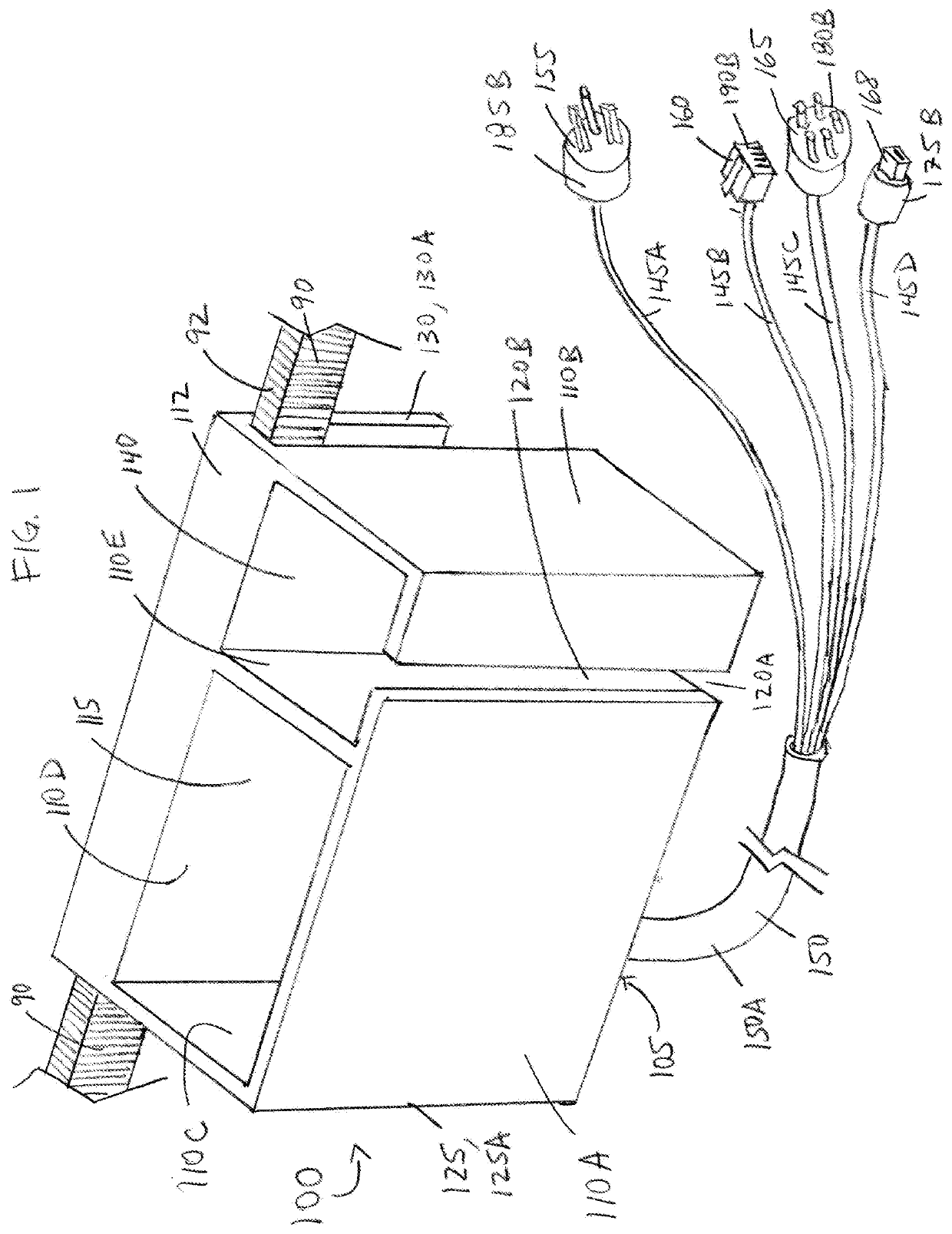
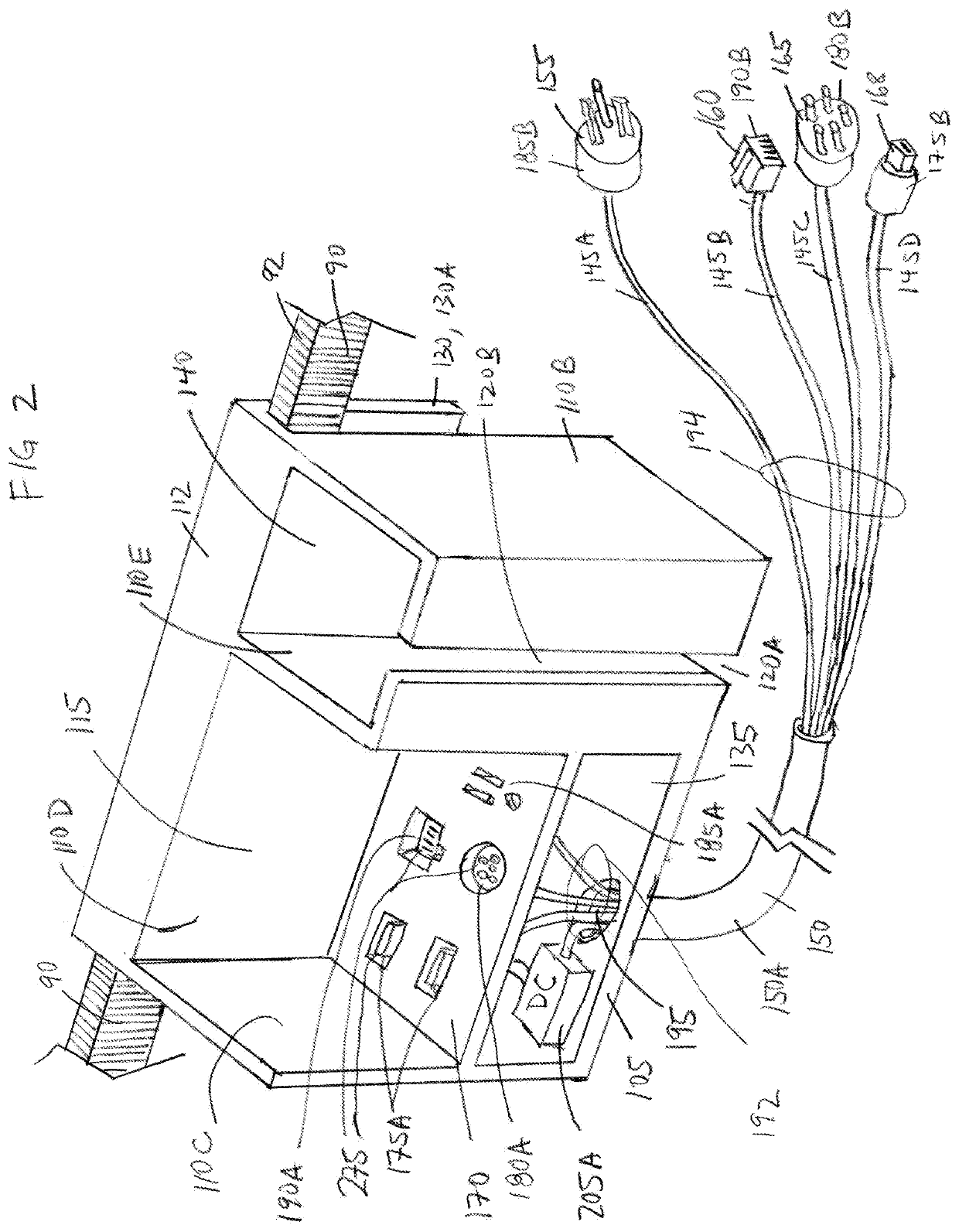
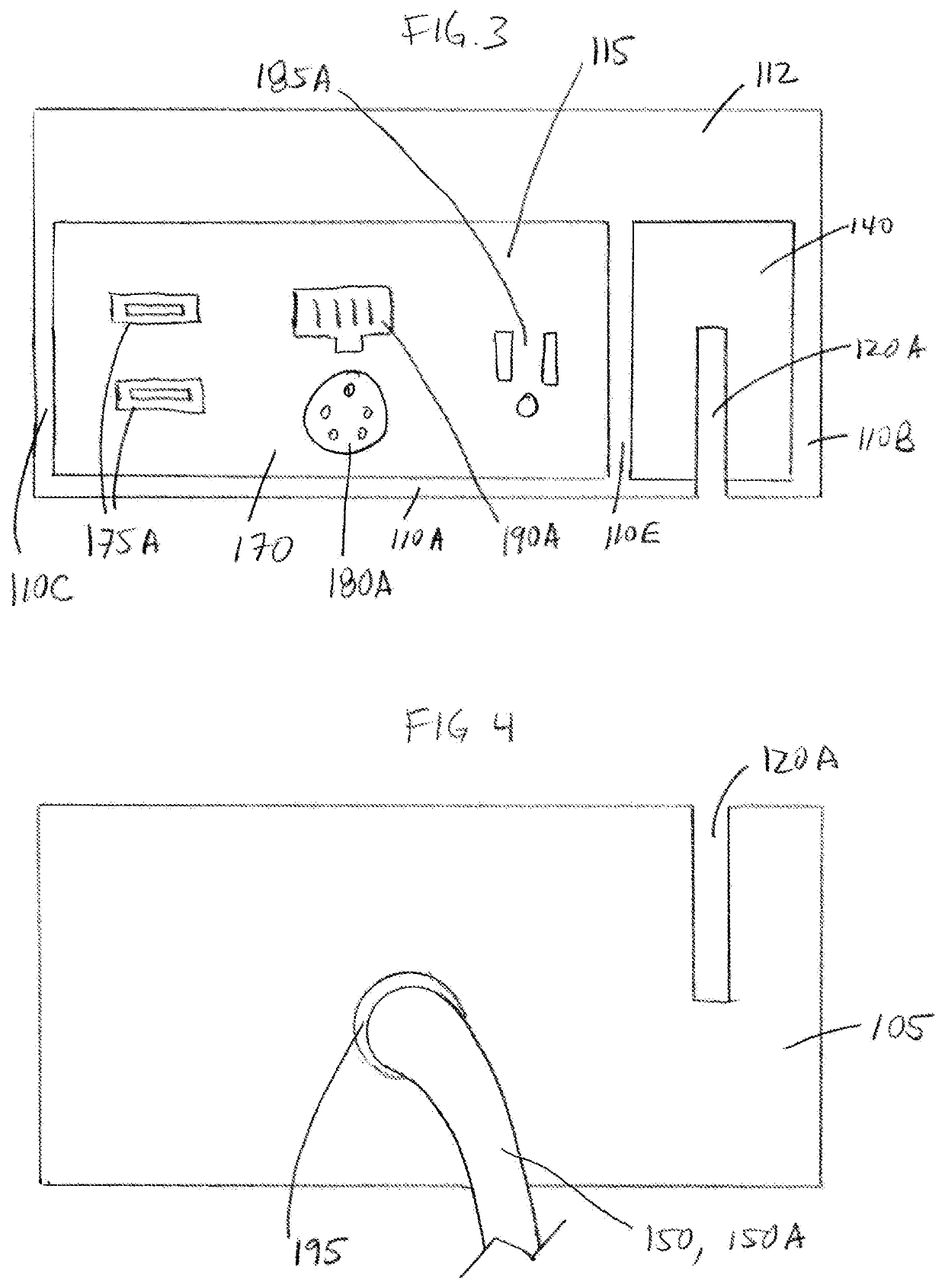
[0043]Referring to FIGS. 1-5, a representative first embodiment of a hospital bed caddy 100 comprises a housing 125, 125A formed by a base panel (or base) 105 coupled to one or more side panels (or side walls) 110, illustrated as a front side panel 110A, lateral side panels 110B and 110C, a rear (or back) side panel 110D, and an optional side (or divider) panel 110E. The side panels 110 coupled to the base panel 105 further form a plurality of compartments 115, 135, 140, illustrated as a first, main or central compartment 115, a second, electrical compartment 135, and an optional third, side compartment 140. One or more compartments 115, 140 of the plurality of compartments 115, 135, 140, may be utilized (by the patient) for organization and storage of a wide variety of possessions, devices, other items, etc., with the second, electrical compartment 135 utilized for housing one or more electrical interfaces (or, equivalently, connectors) 175A, 180A, 185A, 190A, as discussed in great...

third embodiment

[0057]FIG. 7 is an isometric view illustrating a representative third embodiment of a hospital bed caddy 300. The hospital bed caddy 300 differs from the hospital bed caddy 100 insofar as the hospital bed caddy 300 includes an optional fourth compartment 250 formed using an additional side (or divider) panel 110F, and further comprises an extension arm 215 with a mobile device mount 225, with the extension arm 215 illustrated in an extended position in FIG. 7. The extension arm 215 has multiple, jointed (or hinged) segments 226, 228 as illustrated (using joints or hinges 242, 244, along with the pivot coupling or mount 220), to allow for compact folding of the extension arm (as illustrated in FIG. 11) and extending of the extension arm 215 (as illustrated in FIGS. 7 and 13) to reach from the housing 125C to a patient seated or lying in the hospital bed. Any suitable joints or hinges 242, 244 may be utilized for the extension arm 215. A first end 222 of the extension arm 215 is coupl...

fourth embodiment

[0061]FIG. 8 is an isometric view illustrating a representative fourth embodiment of a hospital bed caddy 400. The hospital bed caddy 400 also differs from the hospital bed caddy 100 insofar as the hospital bed caddy 400 includes an optional fourth compartment 250 formed using an additional side (or divider) panel 110F. The hospital bed caddy 400 further differs from the hospital bed caddy 100 insofar as: (1) one or more lids 230 are provided to cover a corresponding compartment (e.g., covering compartment 250), with a representative lid 230 rotatably coupled to the housing 125D using a hinge 232; and (2) one or more of the base panel 105 (not separately illustrated) and / or side panels 110M, 110N further include a plurality of perforations (or holes) 235, such as to provide additional or greater airflow within one or more of the compartments 115, 140, 250. These perforations (or holes) 235 may be helpful in dissipating any condensation which may form around contents held in the hosp...


PUM


Abstract

A representative embodiment of a hospital bed caddy is disclosed, comprising: a housing having a base panel with a first opening and one or more side panels coupled to the base panel to form a plurality of compartments, including first and second compartments; a bed rail attachment; a plurality of electrical interfaces arranged in the second compartment; a plurality of electrical cables arranged in the first opening, with each electrical cable coupled within the second compartment to a corresponding electrical interface; and a cable harness or sheath coupled around the plurality of electrical cables. A cover panel may be included, with the cover panel separating the second compartment from the first compartment, and with the electrical interfaces being user-accessible from within the first compartment. Various embodiments may also include one or more slots in the various panels and a moveable extension arm with a mobile device mount.

Description

CROSS-REFERENCE TO RELATED APPLICATIONS[0001]This application is a nonprovisional of and claims the benefit of and priority to U.S. Provisional Patent Application No. 63 / 187,642, filed May 12, 2021, inventors Michael Shannon McCorquodale et al., titled “Electrically Active Hospital Bed Caddy with Adjustable Mobile Device Mount and Wire Harness”, and is a nonprovisional of and claims the benefit of and priority to U.S. Provisional Patent Application No. 63 / 187,687, filed May 12, 2021, inventors Michael Shannon McCorquodale et al., titled “Electrically Active Hospital Bed Caddy with Adjustable Mobile Device Mount and Wire Harness”, all of which are hereby incorporated herein by reference in their entireties with the same full force and effect as if set forth in their entireties herein.FIELD OF THE INVENTION[0002]The present invention, in general, relates to bed storage caddies and, more specifically, relates to a hospital bed caddy having electrically active charging and communication...

Claims


Application Information

Patent Timeline
Patent Type & Authority Applications(United States)
IPC IPC(8): A61G7/05A61B50/22
CPCA61G7/0507A61B50/22A61G7/0503A61G12/002
Inventor MCCORQUODALE, MICHAEL SHANNONBACKES, SAM
Owner ARBOR DEVICES LLC
Why Eureka
Try Eureka