
Sheet manufacturing apparatus and sheet manufacturing method

Pending Publication Date: 2022-11-17
SEIKO EPSON CORP
View PDF2 Cites 0 Cited by
  • Summary
  • Abstract
  • Description
  • Claims
  • Application Information

AI Technical Summary

Benefits of technology

[0061]The sheet manufacturing apparatus 100 includes the accumulating unit 60 that causes a defibrated product to accumulate in a dry manner and forms the web W, the moisture adding unit 78 that adds moisture from the side of one surface Wa of the web W that has been formed, such that the moisture content of the web W is equal to or more than 12 mass % and equal to or less than 40 mass %, and the heating unit 82 that heats the web W to which moisture has been added. The heating unit 82 has the first portion 84 that comes in contact with the one surface Wa of the web W and the second portion 86 that comes in contact with another surface Wb of the web W, and the heating unit 82 heats the web W in a state of the surface temperature of the first portion 84 being higher than the surface temperature of the second portion 86.
[0062]As a result, as indicated in examples and comparative examples described later, in the sheet manufacturing apparatus 100, compared to when the web W is heated in a state of the surface temperature of the first portion and the surface temperature of the second portion being the same, the paper dust amount generated in the sheet S can be reduced. In the sheet manufacturing apparatus 100, the one surface Wa side, which has a larger moisture content, is heated at a temperature higher than the temperature on the another surface Wb side. Accordingly, the moisture content can be made appropriate for generating a hydrogen bond on the one surface Wa side and the another surface Wb side. As a result, a plurality of fibers can be firmly bound by a hydrogen bond, and the paper dust mount can be reduced.
[0063]In the sheet manufacturing apparatus 100, the heating unit 82 heats the web W in a state of the difference between the surface temperature of the first portion 84 and the surface temperature of the second portion 86 being equal to or more than 10° C. and equal to or less than 50° C. As a result, in the sheet manufacturing apparatus 100, the paper dust amount can be further reduced.
[

Problems solved by technology

However, when an accumulated defibrated product is given moisture from one surface side and heated as described above,

Method used


Image

  • Sheet manufacturing apparatus and sheet manufacturing method
  • Sheet manufacturing apparatus and sheet manufacturing method
  • Sheet manufacturing apparatus and sheet manufacturing method

Examples


Example

[0012]Hereinafter, embodiments of the present disclosure will be described in detail with reference to the drawings. Note that the embodiments described below do not unreasonably limit the content of the present disclosure described in the scope of claims. In addition, all of the configurations described below are not necessarily the essential constituent elements of the present disclosure.

1. Sheet Manufacturing Apparatus

1.1. Overall Configuration

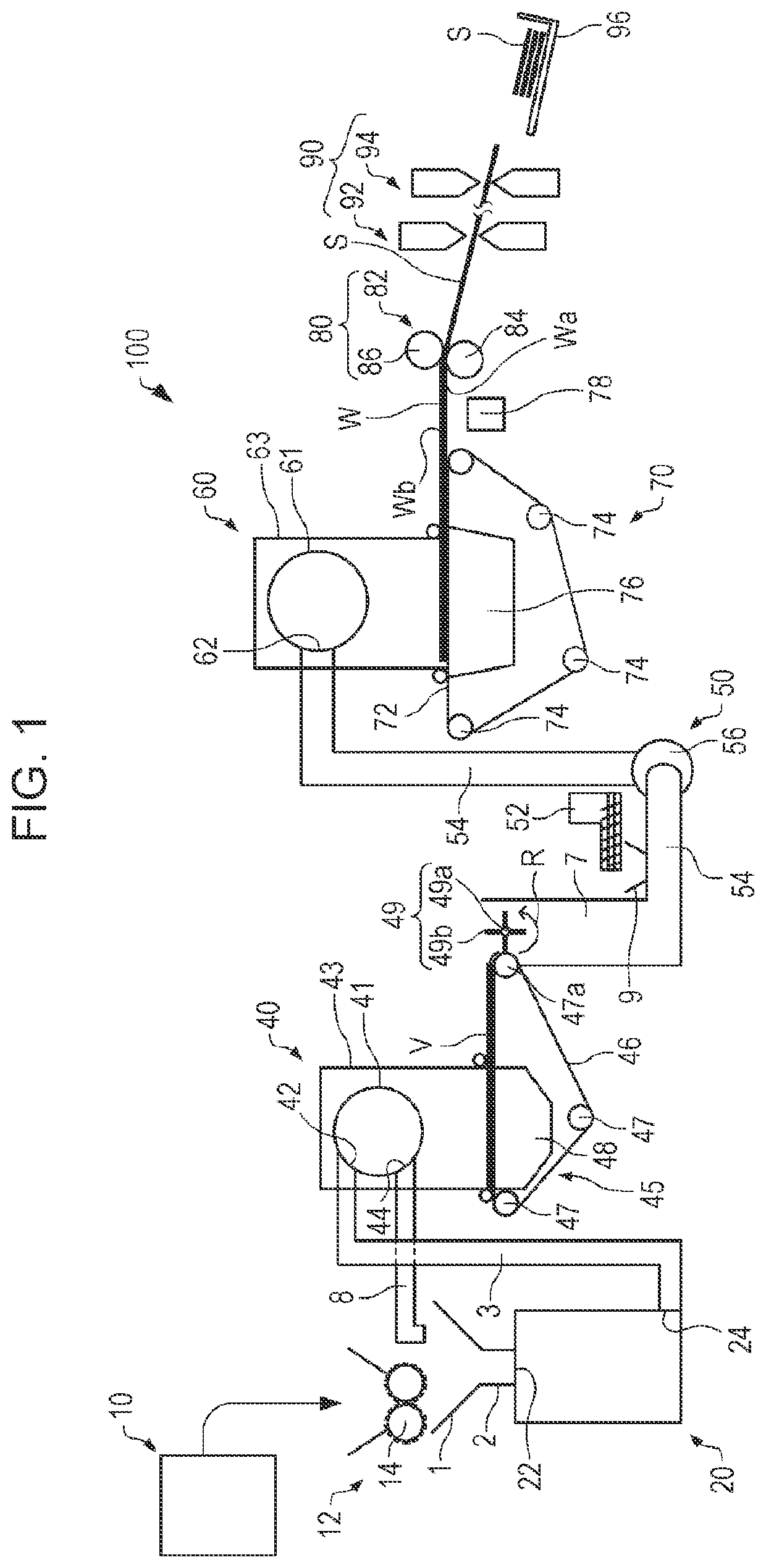
[0013]First, a sheet manufacturing apparatus according to the present embodiment will be described with reference to the drawings. FIG. 1 is a diagram schematically illustrating a sheet manufacturing apparatus 100 according to the present embodiment.

[0014]As illustrated in FIG. 1, the sheet manufacturing apparatus 100 includes, for example, a supply unit 10, a crushing unit 12, a defibrating unit 20, a sorting unit 40, a first web forming unit 45, a rotor 49, a mixing unit 50, an accumulating unit 60, a second web forming unit 70, a moistur...


PUM


Abstract

A sheet manufacturing apparatus including an accumulating unit that causes a defibrated product to accumulate in a dry manner and forms a web, a moisture adding unit that adds moisture from a side of one surface of the formed web such that a moisture content of the web is equal to or more than 12 mass % and equal to or less than 40 mass %, and a heating unit that heats the web to which moisture is added. The heating unit has a first portion that comes in contact with the one surface of the web and a second portion that comes in contact with another surface of the web, and the heating unit heats the web in a state of a surface temperature of the first portion being higher than a surface temperature of the second portion.

Description

[0001]The present application is based on, and claims priority from JP Application Serial Number 2021-083188, filed May 17, 2021, the disclosure of which is hereby incorporated by reference herein in its entirety.BACKGROUND1. Technical Field[0002]The present disclosure relates to a sheet manufacturing apparatus and a sheet manufacturing method.2. Related Art[0003]A dry sheet manufacturing method has been proposed for reducing the size and saving energy.[0004]For example, JP-A-2012-144819 describes a paper recycling apparatus including a dry defibrating unit that crushes and defibrates paper, a paper forming unit that forms paper with a product defibrated by the dry defibrating unit, a moisture sprayer that sprays moisture on the formed paper, and a heater roller that heats the paper on which moisture has been sprayed by the moisture sprayer.[0005]However, when an accumulated defibrated product is given moisture from one surface side and heated as described above, a large amount of p...

Claims


Application Information

Patent Timeline
IPC IPC(8): D21F7/00D21F1/66D21F5/00D21F5/18
CPCD21F7/003D21F1/66D21F5/004D21F5/18D21F7/006D04H1/558D04H1/72D04H1/58D21F9/00Y02W30/64
Inventor NAGAI, YOSHIYUKIOMAGARI, NAOKONAKAMURA, MASAHIDE
Owner SEIKO EPSON CORP
Features
  • Generate Ideas
  • Intellectual Property
  • Life Sciences
  • Materials
  • Tech Scout
  • Unparalleled Data Quality
  • Higher Quality Content
  • 60% Fewer Hallucinations
Learn More