Antenna device and method for portable radio equipment

Inactive Publication Date: 2000-01-18
BLACKBERRY LTD
View PDF12 Cites 30 Cited by
  • Summary
  • Abstract
  • Description
  • Claims
  • Application Information

AI Technical Summary

Problems solved by technology

These two characteristics can be difficult to combine wherefore a compromise often becomes necessary.
In the retracted position the receiving sensitivity is however very bad.
There is consequently a risk that an incoming call request cannot be received by the mobile telephone when the antenna is retracted.
In the folded-down position the receiving sensitivity is, however, very bad.
There is consequently a risk that an incoming call request cannot be received by the mobile telephone when the antenna is folded down.
No construction show

Method used


Image

  • Antenna device and method for portable radio equipment
  • Antenna device and method for portable radio equipment
  • Antenna device and method for portable radio equipment

Examples


first embodiment

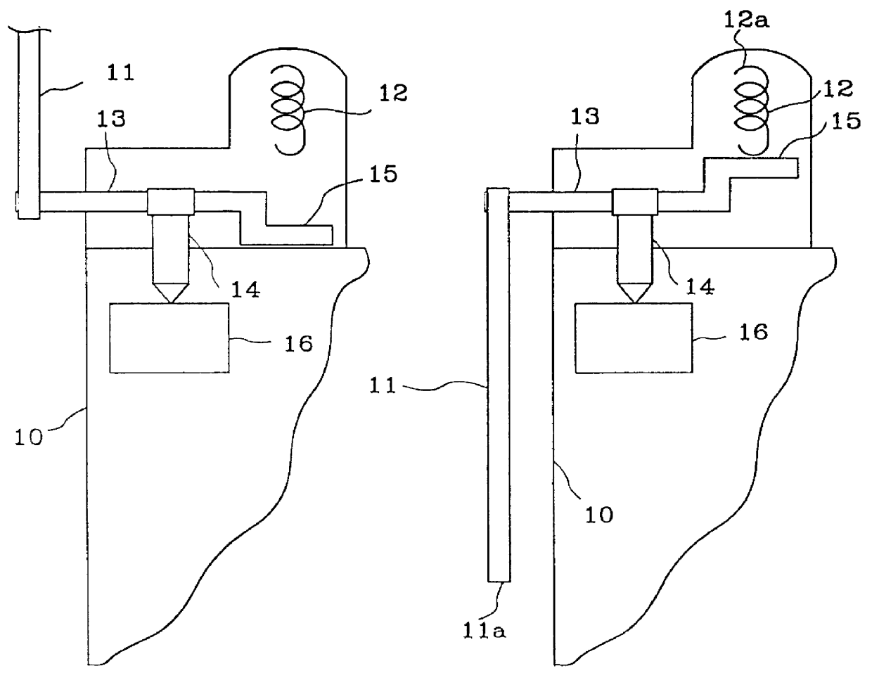
FIG. 1 shows schematically an antenna device according to the present invention. The antenna device is shown mounted on a portable radio equipment 10 which in this example is a mobile telephone. The antenna device comprises a primary antennna 11 and a secondary antenna 12. The primary antenna in this example is a swivel antenna and the secondary antenna is a helical antenna. The primary antenna can be used during calls in progress and can be said to be a conversation antenna or active antenna. The secondary antenna can be used when the mobile telephone is ready for reception of and incoming call request and can be said to be a paging antenna.

The primary antenna 11 can be connected to the radio circuits of the mobile telephone via a rotatable shaft 13 and an antenna connection 14. The secondary antenna 12 can be connected to the radio circuits 16 of the mobile telephone via a switching means 15, shaft 13 and antenna connection 14.

In FIG. 1 is primary antenna 11 is shown in a first or...

second embodiment

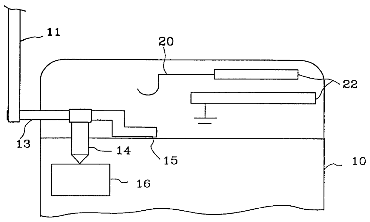
FIG. 3 shows schematically an antenna device according to the present invention. The antenna device is shown mounted on a mobile telephone 10. The antenna device comprises a primary antenna 11 and a secondary antenna 22. The primary antenna in this example is a swivel antenna and the secondary antenna is a patch antenna.

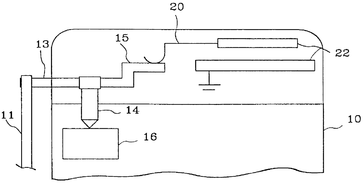
In the same way as earlier the primary antenna is connected to the radio circuits of the mobile telephone by a rotatable shaft 13 and an antenna connection 14. The secondary antenna can be connected to the mobile telephone radio circuits 16 via a switching means 15, the shaft 13 and a connection means 20.

FIG. 3 shows the primary antenna 11 in a first or raised-up position, wherein the primary antenna is connected to radio circuits 16 and wherein the secondary antenna 22 is not connected to radio circuits. The primary antenna is in this position during calls in progress whereby good receiving sensitivity is obtained.

When the primary antenna is folded down to a second ...

third embodiment

FIG. 5 shows schematically an antenna device according to the present invention. The antenna device is shown mounted on a mobile telephone 10. The antenna device comprises a primary antenna 31 and a secondary antenna 22. The primary antenna in this example is a telescopic antenna and the secondary antenna is a patch antenna.

According to the present example of an embodiment the primary antenna 31 can be connected to the radio circuits 16 of a mobile telephone via en antenna connection 33. The secondary antenna 22 can be connected to the radio circuits 16 of the mobile telephone via a switching means which can be produced by means of a contact means 33 and an insulating means 34. The antenna connection 33 and contact means 32 can be some type of contact foil which can be brought into contact with the primary antenna when it takes up the first and second positions. The insulating means is arranged by the primary antenna so that the contact means 32 is brought out of contact with the pr...


PUM


Abstract

The invention relates to an antenna device for portable radio equipment such as mobile telephones (10) and a method for producing the antenna device. Mobile telephone antennas should have good receiving sensitivity and at the same time be compact. An antenna which can be folded down, folded up or retracted into a mobile telephone becomes compact but the receiving sensitivity becomes bad. A solution is an antenna device which comprises two antennas, a primary antenna (11) and a secondary antenna (12). The primary antenna can take up two positions and is always connected to the radio circuits (16) of the mobile telephone. The secondary antenna is a small and compact antenna. When the mobile telephone is in the paging position, the primary antenna is placed in the folded down, folded up or retracted-in position, wherein the secondary antenna is also connected to the radio circuits. The two antennas form an antenna device which has good receiving sensitivity and is compact.

Description

The present invention relates to an antenna device intended to be used in portable radio equipment, such as mobile telephones etc. The invention relates also to a method for producing said antenna device.STATE OF THE ARTAn antenna which is to be used in portable radio equipment should have good receiving sensitivity and at the same time be compact. These two characteristics can be difficult to combine wherefore a compromise often becomes necessary.The expression portable radio equipment includes all portable equipment which is arranged for communication such as for example mobile telephones, pagers, communicators, that is to say so called organizers with inbuilt telephones and telefax and printer apparatuses. Said equipment can be used in some type of radio network, such as for example cellular networks, satellite networks or smaller, local networks.Today there are several types of antenna on the market, such as for example helical antennas, telescopic antennas, swivel antennas and ...

Claims


Application Information

Patent Timeline
IPC IPC(8): H01Q21/28H01Q1/24H01Q21/00H01Q1/08
CPCH01Q1/084H01Q1/242H01Q21/28
Inventor JOHANSSON, NILS ANDERS
Owner BLACKBERRY LTD
Why Eureka
Try Eureka