

Support for load transfer device for concrete constructions
- Summary
- Abstract
- Description
- Claims
- Application Information
AI Technical Summary
Problems solved by technology
Method used
Image

Examples
Embodiment Construction
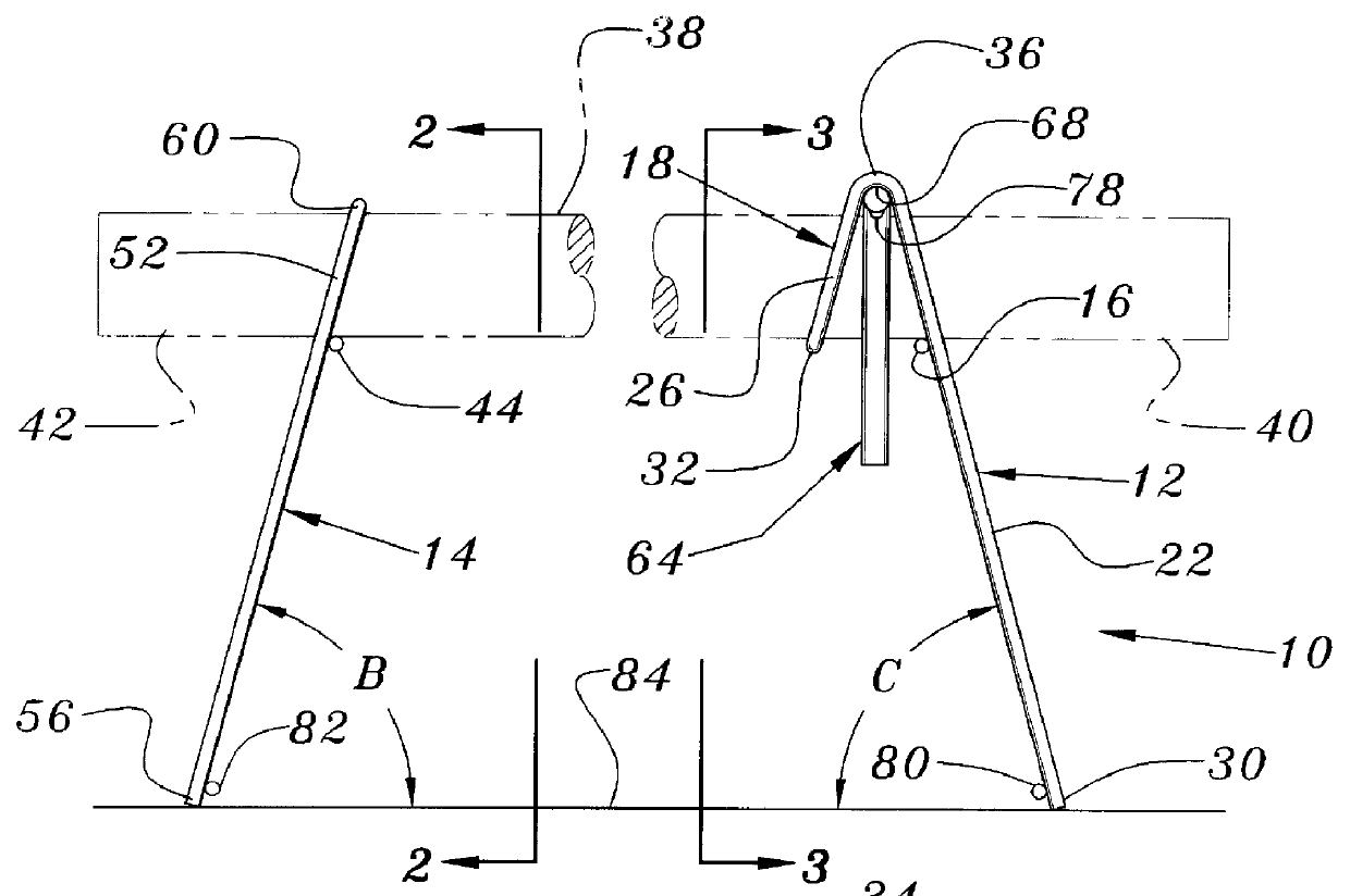
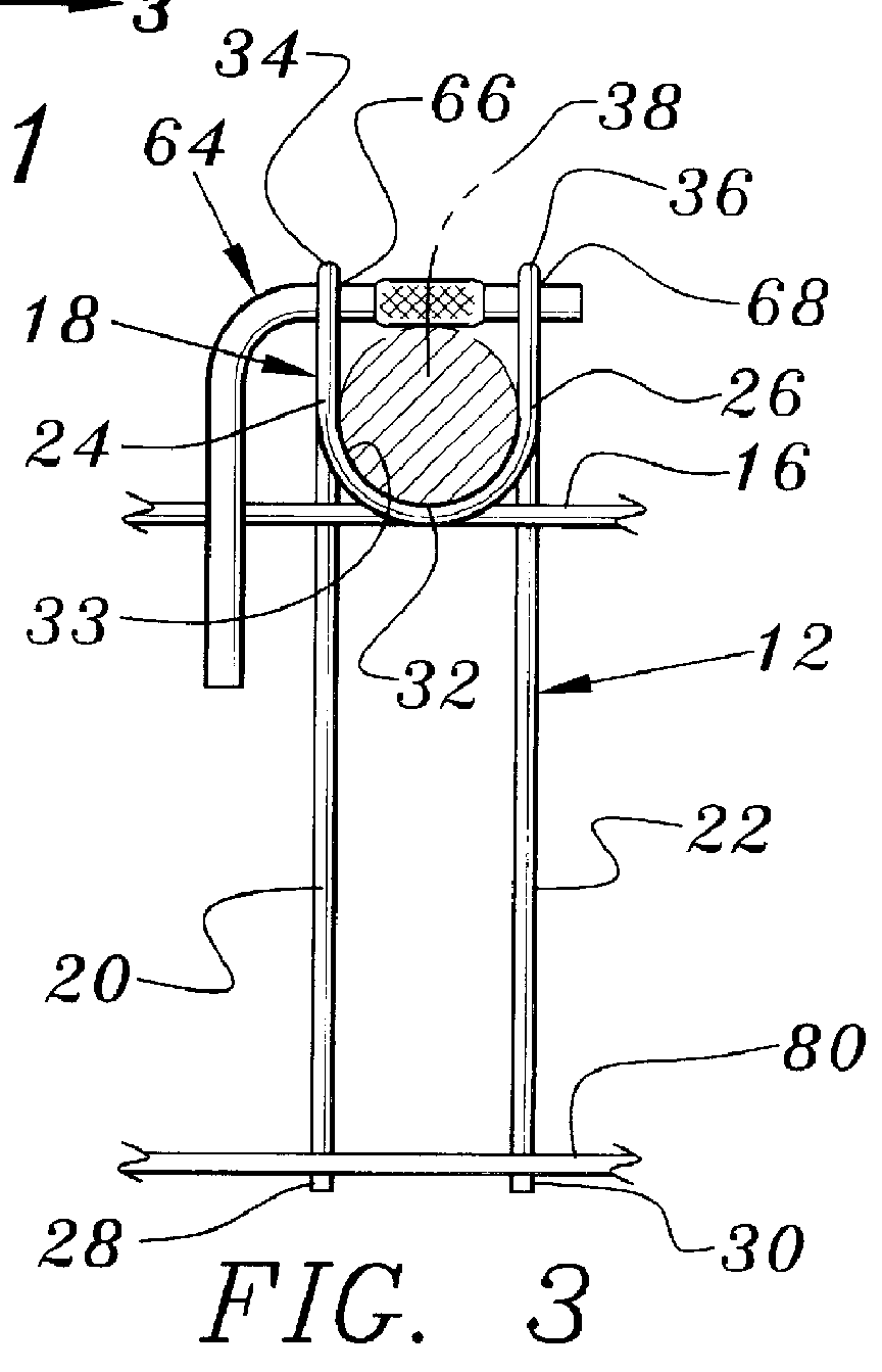
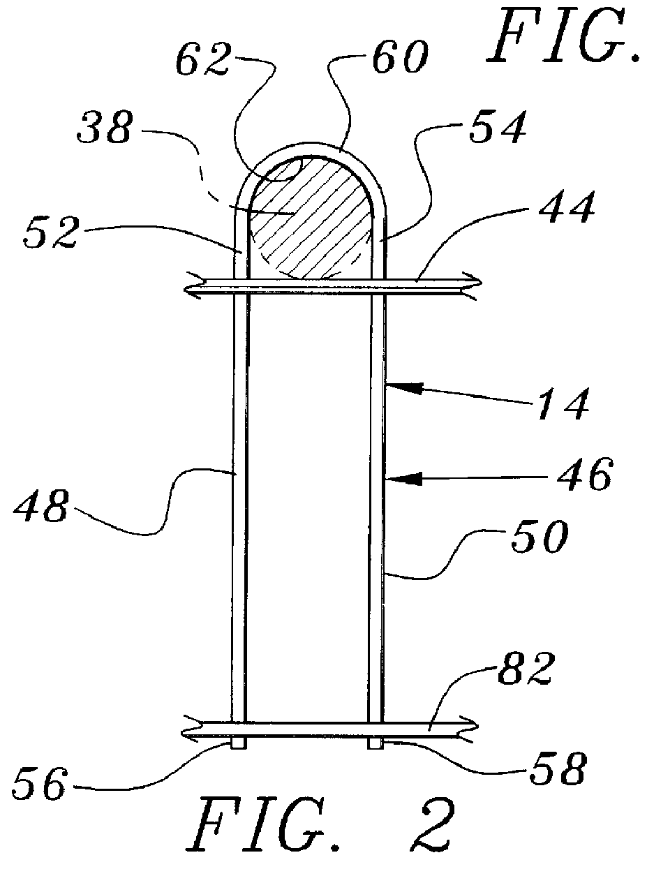
A preferred embodiment for the supports for a load transfer device is illustrated in the drawing FIGS. 1-3, 6-9, 11 and 12. FIGS. 4 and 5 illustrate a second preferred embodiment of the invention of FIG. 1. FIG. 10 illustrates a second preferred embodiment of the pin lock of this invention and the reference numbers of this figure are incremented by 100 to indicate similar parts. The supports for a load transfer device are indicated generally as 10 in the views of FIGS. 1-3, 11 and 12. Referring first to FIG. 1, it can be seen that the supports for a load transfer device 10 comprise a first support 12 and a second support 14. As seen in FIG. 3, the first support comprises a first member 16 and an element 18 that is attached to the first member 16. The element 18 comprises a first leg 20 and a second leg 22, each having a respective first end 24 and 26 and a respective second end 28 and 30. In the preferred embodiment illustrated, the legs 20 and 22 are generally parallel to one anoth...
PUM
 Abstract
Description
Claims
Application Information