System of protecting the edges and construction joints of cast in place concrete slabs

a technology of construction joints and edges, applied in resiliently-mounted floors, walls, ways, etc., can solve problems such as dangerous to employees, overturning of loaded forklift trucks, and damage to trucks and carried products, and achieve the effect of more accurate alignment of joint edge assembly members and accurate positioning

Active Publication Date: 2012-11-06
ILLINOIS TOOL WORKS INC
View PDF12 Cites 41 Cited by
  • Summary
  • Abstract
  • Description
  • Claims
  • Application Information

AI Technical Summary

Problems solved by technology

The joint openings, however, create discontinuities in the slab surface, which can cause the wheels of forklift trucks and other vehicles to impact the joint edges and chip small pieces of concrete from the edge of each slab, particularly if the joint edges are not aligned.
This damage to the edges of slabs is commonly referred to as “joint spalling.” Joint spalling often interrupts the normal working operations of many facilities by slowing down forklift and other truck traffic, and / or causing damage to trucks and the carried products.
Severe joint spalling and uneven joints can even cause loaded forklift trucks to be overturned and can be dangerous to employees.
Moreover, joint spalling can be very expensive to repair.
However, the standard installation procedure for these steel bars or angles is both time-consuming and expensive.
If a weld is not completely removed by grinding, or if grinding is not completed shortly after the second slab is cast, then the joint remains locked together and tensile stress accumulates in the slabs, which often leads to unacceptable slab cracking.
Furthermore, if the joint edge members are not evenly aligned during the tack welding, a permanent slab discontinuity may result in the finished product, which may also lead to increased impact with the joint edges.

Method used


Image

  • System of protecting the edges and construction joints of cast in place concrete slabs
  • System of protecting the edges and construction joints of cast in place concrete slabs
  • System of protecting the edges and construction joints of cast in place concrete slabs

Examples


Embodiment Construction

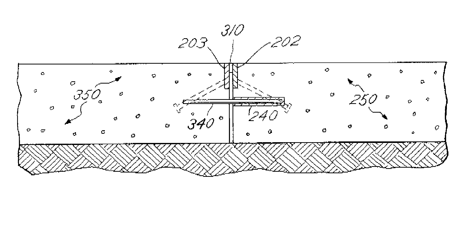
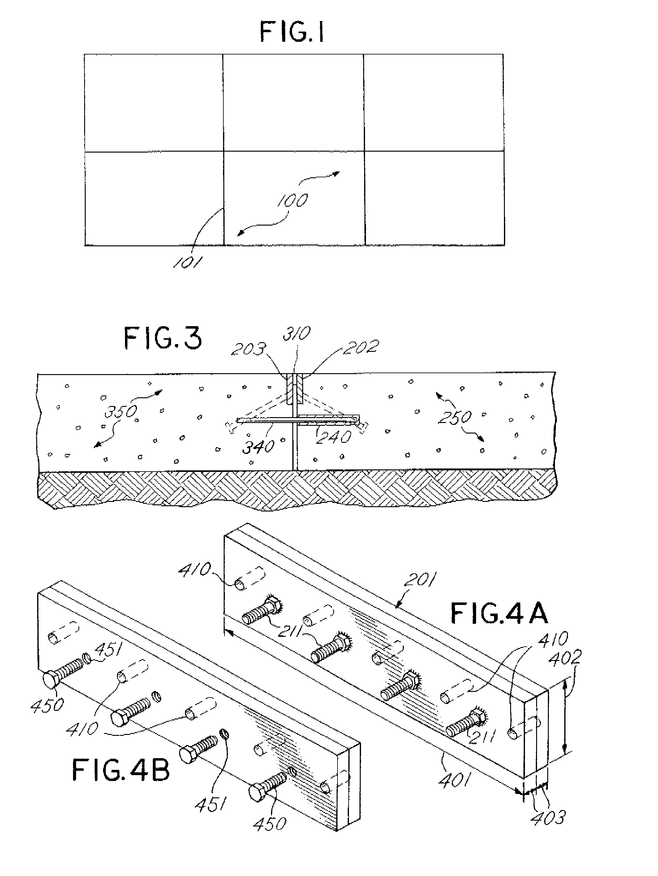
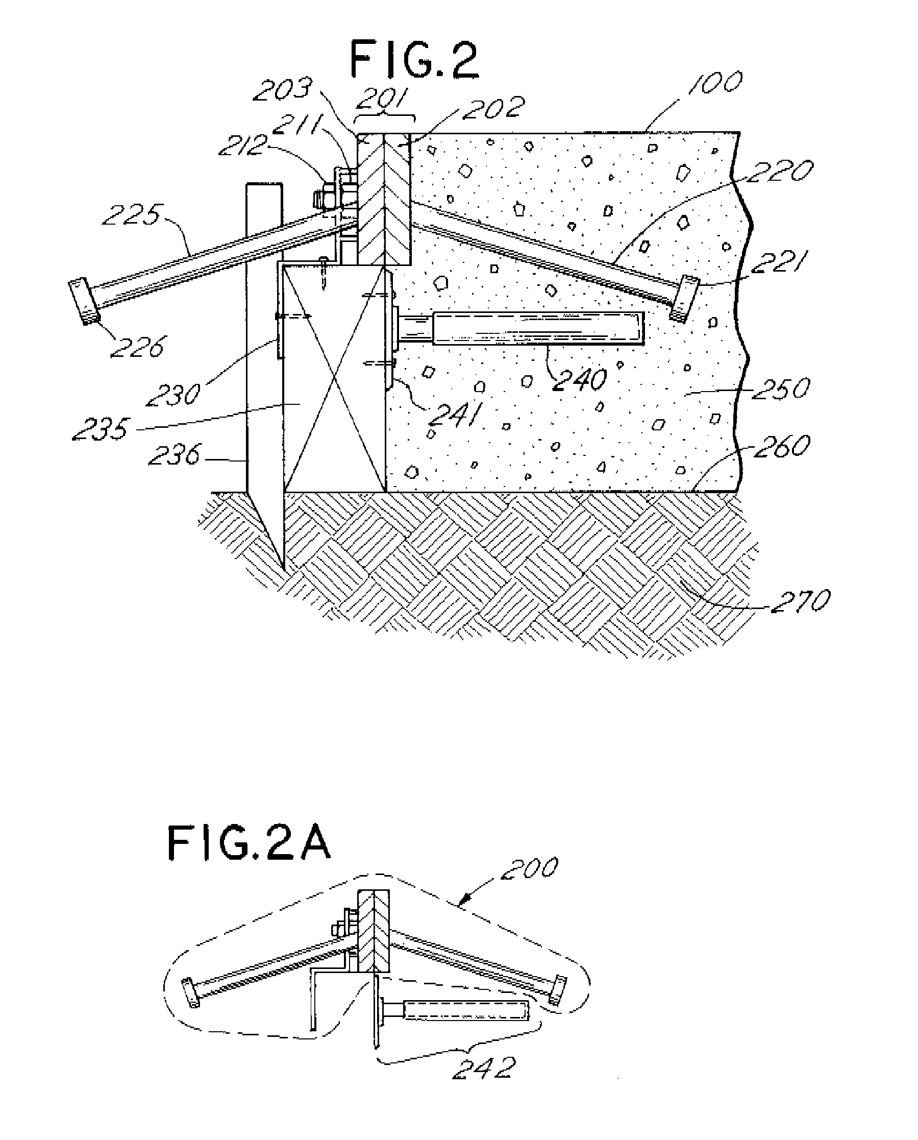
[0023]Preferred designs for a form assembly made in accordance with the claimed invention are shown in the drawings. In FIG. 2A, the preferred embodiment of the form assembly 200 for use with temporary formwork is shown. Referring to FIG. 2, the form assembly 200 includes a longitudinal joint rail 201, which is comprised of two joint edge members 202, 203. The joint edge members 202, 203 are typically steel bar sections, but any other suitable steel section, such as an angle section, can be used. FIGS. 4A, 4B show the three, dimensional components of the joint rail 201, the longitudinal dimension 401, the major latitudinal dimension 402, and the minor latitudinal dimension 403. In situ, the longitudinal dimension 401 is oriented along the length of the joint 101 between adjacent concrete slab sections 100 (shown in FIG. 1) and parallel to the ground surface 260, which defines a generally flat reference plane. The major latitudinal dimension 402, when in situ, extends generally perpe...


PUM


Abstract

An improved joint edge assembly, of the type used in the construction of concrete slabs, is disclosed. The assembly comprises a longitudinal joint rail, preferably of steel, which is supported off the ground by formwork. The joint rail comprises first and second joint edge members that are connected to each other by interference-type connectors with self-release elements. A plurality of studs extends downward and outward from each of the joint edge members into the concrete slabs provide a positive mechanical connection between the slab and the joint rail. As the concrete shrinks during hardening, the self-release elements of the interference-type connectors allow the joint to freely open. The joint edge assembly thus provides a self-releasing joint between adjacent slab sections, and protects the edges of the adjacent slab sections from damage. A dowel aligner may also be integrated into the assembly, to allow proper positioning of dowels within the slab.

Description

CROSS REFERENCE TO RELATED APPLICATIONS[0001]This application is a continuation-in-part of, and claims benefit of, U.S. application Ser. No. 10 / 885,823, filed Jul. 7, 2004, now abandoned, incorporated herein by reference, which is a continuation of, and claims benefit of, U.S. application Ser. No. 10 / 210,464, filed Jul. 31, 2002, now U.S. Pat. No. 6,775,952, incorporated herein by reference, which is based on, and claims the benefit of, U.S. Provisional Application Ser. No. 60 / 309,397, filed on Aug. 1, 2001, entitled “System of Protecting the Edges of Cast in Place Concrete Slab on Ground, Construction Joints.BACKGROUND OF THE INVENTION[0002]1. Field of the Invention[0003]This invention relates generally to the construction of concrete slabs. More particularly, the invention relates to an improved joint edge assembly that protects the joint edges, permits more accurate alignment of the joint edge assembly members, and allows the joint edges to both self-open and move laterally with ...

Claims


Application Information

Patent Timeline
Patent Type & Authority Patents(United States)
IPC IPC(8): E04B1/682
CPCE01C11/14E04B1/48E04B2005/322E04B2005/324E04B1/483
Inventor BOXALL, RUSSELLPARKES, NIGEL A.HARRISON, PATRICK
Owner ILLINOIS TOOL WORKS INC
Why Eureka
Try Eureka