Wellborne mills & methods

Inactive Publication Date: 2000-02-15
WEATHERFORD TECH HLDG LLC
View PDF115 Cites 38 Cited by
  • Summary
  • Abstract
  • Description
  • Claims
  • Application Information

AI Technical Summary

Benefits of technology

Any such mill with one or more side fluid flow ports to fa

Problems solved by technology

Coring occurs when the piece of tubular moving up into a mill damages

Method used


Image

  • Wellborne mills & methods
  • Wellborne mills & methods
  • Wellborne mills & methods

Examples


Embodiment Construction

Referring now to FIGS. 1A-1H and 2A and 2B, a tool 10 according to the present invention has a whipstock 20 according to the present invention with a pilot block 24 welded near a top 26 thereof. The whipstock has a concave face 22. The pilot block 24 has bolt holes 28.

The tool 10 has a starting bar 60 which has a body 62 which is secured to the whipstock 20 by bolts 69 through holes 63 extending into holes 28 in the pilot block 24. A groove 64 encircles the body 62. A stop bar 29 (see FIG.4) extends through a stop pin hole 66.

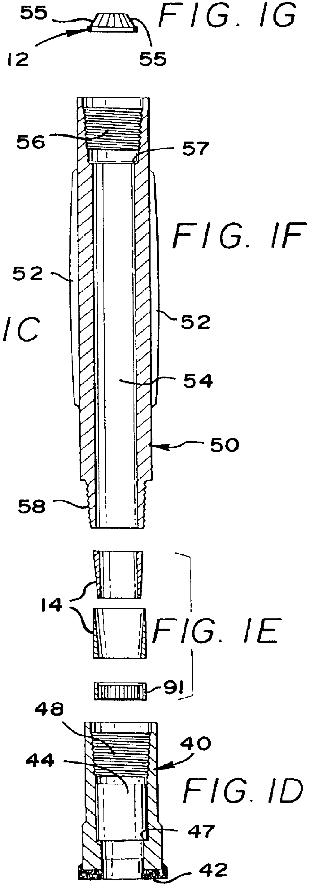
The tool 10 has the milling apparatus 30 which includes at least one and preferably two or more mills so that a milling operation for producing a sidetracking window in casing can be accomplished in a dual or single tool trip into a cased wellbore. As shown in FIG. 1 and 2, the milling apparatus 30 includes a starting mill 40 connected to and below a hollow finishing mill 50. Interior threads 48 of the starting mill 40 engage exterior threads 58 of the finishin...


PUM


Abstract

A wellbore mill has been invented that has a body having a top and a bottom and a first fluid flow channel extending longitudinally therethrough from top to bottom, the first fluid flow channel having an upper end and a lower end, the lower end of the first fluid flow channel having an opening sized for receiving a core of material from a tubular member milled by the mill, and at least a portion of the first fluid flow channel offset from the remainder thereof to facilitate separation of the core from the tubular member. A wellbore milling method for milling an opening in a selected tubular of a tubular string in a wellbore has been invented that includes installing a mill on a working string into the wellbore at a selected desired point for milling the opening in the tubular, the mill comprising a body having a top and a bottom and a first fluid flow channel extending longitudinally therethrough from top to bottom, the first fluid flow channel having an upper end and a lower end, the lower end of the first fluid flow channel having an opening sized for receiving a core of material from a tubular member milled by the mill, and at least a portion of the first fluid flow channel offset from the remainder thereof to facilitate separation of the core from the tubular member, and rotating the mill to mill the selected tubular, create the core by thus milling the tubular and separating the core from the tubular being milled.

Description

1. Field of the InventionThis invention is related to milling processes, milling tools and whipstocks; and in one aspect to milling processes which employ a whipstock. In certain embodiments two-trip and single-trip milling methods and systems are disclosed.2. Description of Related ArtMilling tools are used to cut out windows or pockets from a tubular, e.g. for directional drilling and sidetracking; and to remove materials downhole in a well bore, such as pipe, casing, casing liners, tubing, or jammed tools. The prior art discloses various types of milling or cutting tools provided for cutting or milling existing pipe or casing previously installed in a well. These tools have cutting blades or surfaces and are lowered into the well or casing and then rotated in a cutting operation. With certain tools, a suitable drilling fluid is pumped down a central bore of a tool for discharge beneath the cutting blades and an upward flow of the discharged fluid in the annulus outside the tool r...

Claims


Application Information

Patent Timeline
IPC IPC(8): E21B21/10E21B7/06E21B7/10E21B17/02E21B29/00E21B7/04E21B21/00E21B29/06E21B10/46E21B10/04E21B10/50E21B10/60E21B10/00E21B7/08
CPCE21B29/06E21B7/061E21B7/10E21B10/04E21B10/46E21B10/50E21B10/60E21B17/02E21B21/10
Inventor KUCK, MARK D.BLIZZARD, JR., WILLIAM A.CARTER, THURMAN B.MCCLUNG, III, GUY L.
Owner WEATHERFORD TECH HLDG LLC
Why Eureka
Try Eureka