Surface light source device of side light type with belt-like diffusible area

Inactive Publication Date: 2000-02-15
ENPLAS CORP +1
View PDF8 Cites 17 Cited by
  • Summary
  • Abstract
  • Description
  • Claims
  • Application Information

AI Technical Summary

Benefits of technology

It is an object of the present invention to provide a surface light source device of side light type in which nonuniformity

Problems solved by technology

The surface light source device of side light type 1 employing the light guide plate having the aforementioned directional emitting characteristic causes an unsolved problem such that nonun

Method used


Image

  • Surface light source device of side light type with belt-like diffusible area
  • Surface light source device of side light type with belt-like diffusible area
  • Surface light source device of side light type with belt-like diffusible area

Examples


Example

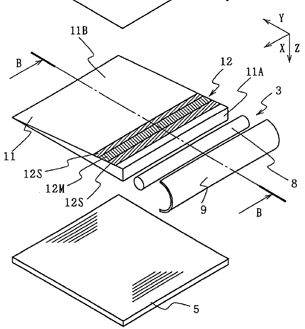
Referring to FIG. 1 showing the first embodiment, a surface light source device of side light type 10 has a reflection sheet 4, light scattering guide plate 11 and prism sheet 5, and they are laminatedly arranged. This basic structure is common to a surface light source device of side light type 1 shown in FIG. 3 except that the light scattering guide plate 11 is employed instead of the light scattering guide plate 2.

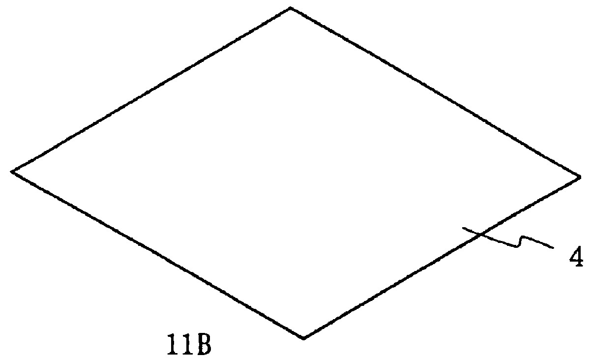
The light scattering guide plate 11 may be the same as the light scattering guide plate 2 shown in FIG. 3 except that a light diffusible area 12 is formed on a part of a slanted surface 11B. The surface other than the light diffusible area 12 may be an approximately plane mirror. As the reflection sheet 4, a member to which a regular reflecting characteristic is given by silver vacuum evaporation is employed.

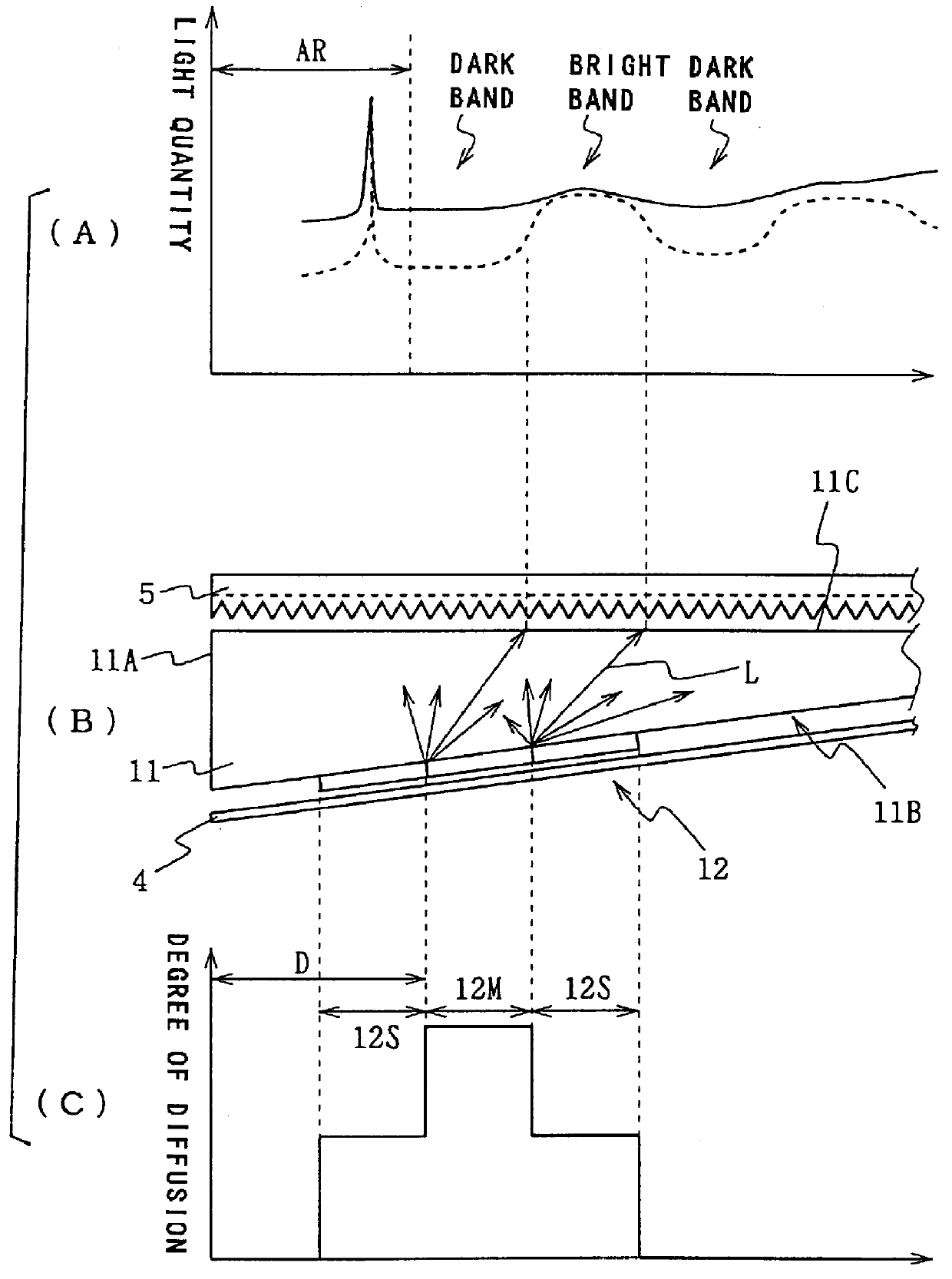
The light diffusible area 12 is composed of a mat-finished surface (rough surface) to which certain roughness is given by the mat process. As shown by the sectional...

Example

Next, referring to FIG. 5, a surface light source device of side light type 20 according to the second embodiment has the reflection sheet 4, a light scattering guide plate 21, the prism sheet 5, a diffusible plate 6 and prism sheet 7, and they are laminatedly arranged. This basic structure is common to the surface light source device of side light type 1 shown in FIG. 3 except that the light scattering guide plate 21 is employed instead of the light scattering guide plate 2, and that two prism sheets 5 and 7 instead of one prism sheet 5 and the diffusible sheet 6 are arranged.

The light scattering guide plate 21 may be the same as the light scattering guide plate 2 shown in FIG. 3 except that a light diffusible area 24 is formed on a portion of an emitting surface 21C. The whole surface excluding the light diffusible area 24 may be approximately a plane mirror. As the reflection sheet 4, a white PET film is employed.

The prism sheets 5 and 7 are single-side prism sheets. The prism su...

Example

Referring to FIG. 7, a surface light source device of side light type 30 according to the third embodiment has the reflection sheet 4, a light scattering guide plate 31, the prism sheet 5, the diffusible plate 6 and the prism sheet 7, and they are laminatedly arranged.

This basic structure is common to that of the second embodiment except that the light scattering guide plate 31 is employed instead of the light scattering guide plate 2.

A light diffusible area 32 is formed on a slanted surface 31B, and a light diffusible area 34 is formed on an emitting surface 31C. The light diffusible area 32 is formed in a belt along the incidence surface 31A. Its width is smaller than the light diffusible area 34 only by an about thickness of the incidence surface 31A. Meanwhile, the light diffusible area 34 is composed of two areas (main diffusible area 34M and supplementary diffusible area 34S) similarly to the light diffusible area 24 in the second embodiment. Constant light diffusibility is gi...


PUM


Abstract

In a surface light source device of side light type applied to a liquid crystal display device, etc., more specifically a surface light source device of side light type having a directivity emitting characteristic, a bright-and-dark-band contrast which is generated in a vicinity of an incidence surface is prevented. In a surface light source device of side light type, light diffusible areas composed on main-and-supplementary diffusible areas are formed on a slanted surface and an emitting surface of a light guide plate having a directivity emitting characteristic. A silver sheet is fixed to a projected portion of a prism sheet along an upper edge, and an illumination light which arrives at the upper edge from a fluorescent lamp is blocked so that the strong brightening of the upper edge is prevented. An illumination light form a lower edge is blocked by a reflector or a frame and reflected diffusively. The light diffusible area may be formed on one of the slanted surface and the emitting surface. Moreover, the light diffusible area may be formed on an additional element such as a reflection sheet.

Description

1. Field of the InventionThe present invention relates to a surface light source device of side light type, more specifically, relates to a surface light source device of side light type in which uniformity of luminance is improved. The present invention is applied to back lighting of a liquid crystal display device, for example.2. Related ArtA surface light source device of side light type has been conventionally applied to a liquid crystal display device, for example, and this device illuminates a liquid crystal panel from a back surface. Its arrangement is suitable for thinning the whole form of the device.In the surface light source device of side light type, a rod-type light source such as a cold cathode tube is employed as a primary light source, and it is arranged beside a light guide plate (plate-type member composed of a light guide material). An illumination light emitted from the primary light source is guided into the light guide plate through the side end surface of the...

Claims


Application Information

Patent Timeline
IPC IPC(8): F21V8/00G02B6/00
CPCG02B6/0036G02B6/0061G02B6/0046G02B6/0053
Inventor ISHIKAWA, TSUYOSHISASAKO, HIROMI
Owner ENPLAS CORP
Why Eureka
Try Eureka