
LED package and backlight assembly for LCD comprising the same

a backlight assembly and light source technology, applied in the field of led (light emitting diodes), can solve the problems of increasing the cost of light source and electric power consumption, the size of the lcd, and the inability to be practically employed, and achieve uniform color and luminance.

Inactive Publication Date: 2007-06-07
SAMSUNG ELECTRONICS CO LTD
View PDF13 Cites 20 Cited by
  • Summary
  • Abstract
  • Description
  • Claims
  • Application Information

AI Technical Summary

Benefits of technology

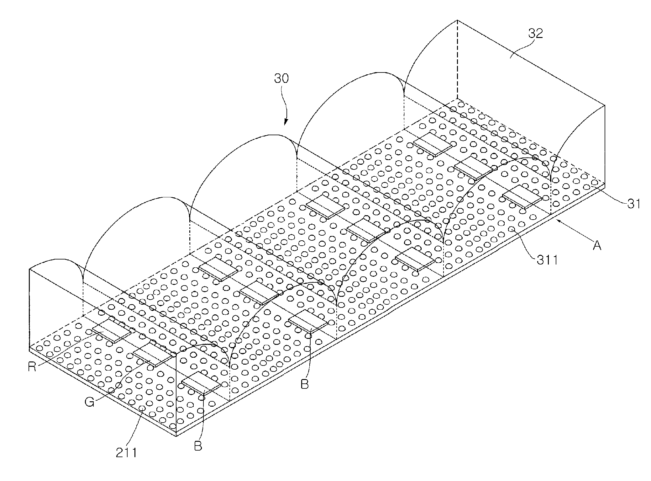
[0013] The present invention has been made in view of the above problems, and it is an object of the present invention to provide an LED package, used as a light source for a backlight assembly of an LCD, which provides a sufficient optical route so that rays generated from one LED or more are sufficiently mixed to produce a white ray having uniform color and luminance.
[0014] It is another object of the present invention to provide a backlight assembly for an LCD comprising the above LED packages.

Problems solved by technology

However, the dense arrangement of the LED packages increases costs of the light source and the electric power consumption rate, thus being incapable of being practically employed.
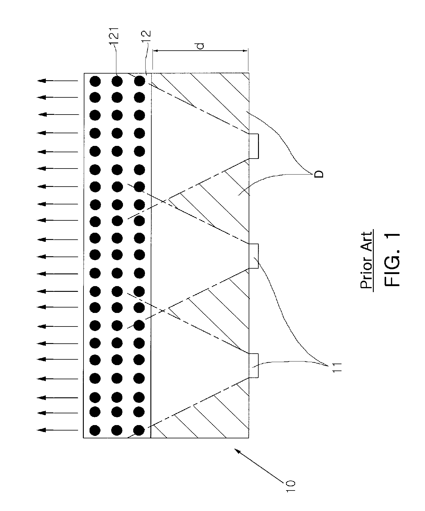
However, the light guide plate 12, separated from the LED packages 11 by the designated distance (d), increases the size of the LCD, and the intensity of light emitted from the LED packages 11 is concentrated on the central area, thus having a negative effect on the miniaturization of the LCD and deteriorating the uniformity of luminance.

Method used


Image

  • LED package and backlight assembly for LCD comprising the same
  • LED package and backlight assembly for LCD comprising the same
  • LED package and backlight assembly for LCD comprising the same

Examples


Embodiment Construction

[0044] Now, preferred embodiments of the present invention will be described in detail with reference to the annexed drawings.

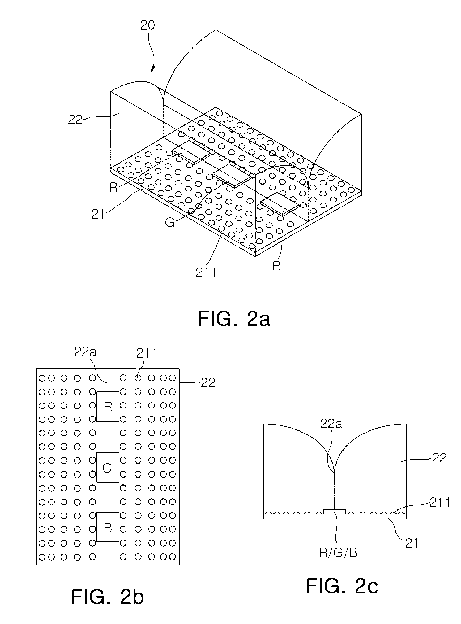
[0045]FIG. 2a is a perspective view of an LED package in accordance with a first embodiment of the present invention. FIG. 2b is a top view of the LED package in accordance with the first embodiment of the present invention.FIG. 2c is a front view of the LED package in accordance with the first embodiment of the present invention. With reference to FIGS. 2a to 2c, the LED package 20 in accordance with the first embodiment of the present invention comprises a substrate 21, LEDs (R, G, and B) separated from each other by designated intervals and arranged in a line on the substrate 21, and a molding portion 22, for sealing the upper surface of the substrate 21 including the LEDs (R, G, and B), provided with an upper surface including two curved surfaces having cylindrical circumferential shapes.

[0046] Although the LED package 20 in accordance with this embodim...


PUM

PropertyMeasurementUnit
transparentaaaaaaaaaa
luminanceaaaaaaaaaa
coloraaaaaaaaaa

Abstract

The present invention relates to an LED package used as a light source used in a backlight assembly for an LCD, and a backlight assembly for an LCD comprising the same. The LED package includes a substrate, one LED or more separated from each other by designated intervals and arranged in a line on the substrate, and a molding portion, for sealing the upper surface of the substrate including the LEDs, provided with an upper surface including two curved surfaces having circular circumferential shapes, wherein each of the curved surfaces has a curvature for totally reflecting light emitted from the LEDs. The LED package assures a sufficient optical traveling route therein without requiring a separate light guide plate, thereby emitting a white ray having uniform luminance.

Description

RELATED APPLICATIONS [0001] This application is a division of U.S. application Ser. No. 10 / 965,257 filed, Oct. 15, 2004, which claims priority from Korean Application Number 2004-38107, filed May 28, 2004, the disclosures of which are hereby incorporated by reference herein in their entirety.BACKGROUND OF THE INVENTION [0002] 1. Field of the Invention [0003] The present invention relates to an LED (Light Emitting Diode) package used as a light source for a backlight assembly for an LCD, and a backlight assembly for an LCD comprising the same. More particularly, the present invention relates to an LED package having improved uniformity in luminance and color of light so as to be used as a light source for a backlight assembly, and a backlight assembly for an LCD comprising the same. [0004] 2. Description of the Related Art [0005] Generally, LCDs (Liquid Crystal Displays) are passive optical elements, which cannot emit light by itself, and thus displaying images using a backlight asse...

Claims


Application Information

Patent Timeline
Patent Type & Authority Applications(United States)
IPC IPC(8): G02F1/1335G02F1/13357H01L25/075H01L33/54H01L33/56H01L33/60
CPCG02F1/133603H01L25/0753H01L33/54H01L2924/0002H01L2924/00G02F1/1335
Inventor KIM, HYUNG SUKPARK, YOUNG SAMHAHM, HUN JOOPARK, JUNG KYUJEONG, YOUNG JUNE
Owner SAMSUNG ELECTRONICS CO LTD
Learn More