Processor support assembly

a technology of supporting assembly and microprocessor, which is applied in the direction of electrical apparatus casing/cabinet/drawer details, coupling device connections, casings/cabinets/drawers, etc., can solve the problems of increasing the overall physical size and weight of the microprocessor assembly to be mounted within the chassis enclosure, and providing only a limited solution

Inactive Publication Date: 2000-02-15
INTEL CORP
View PDF7 Cites 15 Cited by
  • Summary
  • Abstract
  • Description
  • Claims
  • Application Information

AI Technical Summary

Problems solved by technology

As microprocessor technology has developed and the speed of microprocessors has increased, such mounting arrangements have become unworkable, primarily because of the requirements for increased cooling associated with the faster microprocessors.
Having to pair each microprocessor with a heat sink results in an increase in the overall physical size and weight of the microprocessor assembly to be mounted within the chassis enclosure.
However, these prior systems provide only a limited solution to the problems set forth above.
The prior systems fail to provide for a modular arrangement adaptable to a multiprocessor environment, i.e., applications involving systems requiring, e.g., 2, 4, 6 or 8 microprocessors, in which the selective extraction with relative ease of one or more of the plurality of microprocessors might be desired.

Method used


Image

  • Processor support assembly
  • Processor support assembly
  • Processor support assembly

Examples


Embodiment Construction

Illustrative embodiments of the invention are described below. In the interest of clarity, not all features of an actual implementation are described in this specification. It will of course be appreciated that in the development of any such actual embodiment, numerous implementation-specific decisions must be made to achieve the developers' specific goals, such as compliance with system-related and business-related constraints, which will vary from one implementation to another. Moreover, it will be appreciated that such a development effort might be complex and time-consuming, but would nevertheless be a routine undertaking for those of ordinary skill in the art having the benefit of this disclosure.

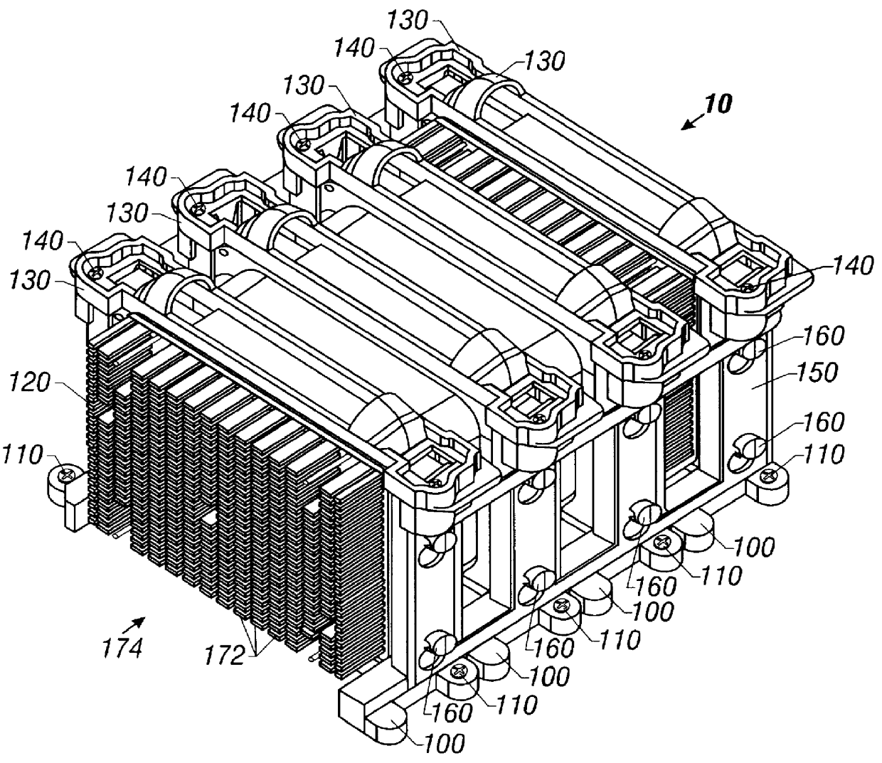
Turning now to the drawings and referring initially to FIG. 1, in a first embodiment of the present invention, an assembly 10 for mounting and supporting microprocessors within a chassis enclosure includes a plurality of retention brackets 100 mounted within the chassis enclosure (not ...


PUM


Abstract

A method and apparatus for supporting within a chassis enclosure a plurality of microprocessors, each operably coupled to a heat sink, includes mounting within the chassis enclosure one or more retention brackets, each retention bracket adapted to receive at least one microprocessor and a cover engaged about the top of at least one microprocessor, the cover being releasably fastenable to the retention bracket, and further including the coupling together of multiple retention brackets to form a bridge-like assembly.

Description

1. Field of the InventionThis invention relates generally to an assembly for supporting one or more microprocessors in a chassis enclosure, and more particularly, to a modular microprocessor cartridge retaining assembly suitable for use in multiple microprocessor cartridge applications in which, inter alia, selective extraction of one or more of a plurality of microprocessor cartridges may be desired.2. Description of the Related ArtMicroprocessors historically have been mounted within systems directly upon printed circuit boards (motherboards). As microprocessor technology has developed and the speed of microprocessors has increased, such mounting arrangements have become unworkable, primarily because of the requirements for increased cooling associated with the faster microprocessors. To cool these faster microprocessors, it is common to pair each microprocessor with a heat sink to form a microprocessor assembly that typically is situated off of the motherboard so as to allow for ...

Claims


Application Information

Patent Timeline
Patent Type & Authority Patents(United States)
IPC IPC(8): H05K7/02
CPCH05K7/023
Inventor DASKALAKIS, GEORGEBROWN, STEPHEN
Owner INTEL CORP
Why Eureka
Try Eureka