Surgical drill with bit penetration control and breakthrough detection

a drill bit and drill bit technology, applied in the field of surgical drills and actuating units with drill bit penetration control and breakthrough detection, can solve the problems of increased risk of error, difficulty in carrying out correct drilling steps without automatic control of drill bits, and increased risk of drilling errors. achieve the effect of precise control of drill bit penetration

Inactive Publication Date: 2000-03-07
SCUOLA SUPERIORE DI STUDI UNIVERSITARI E DI PERFEZIONAMENTO SANTANNA
View PDF3 Cites 92 Cited by
  • Summary
  • Abstract
  • Description
  • Claims
  • Application Information

AI Technical Summary

Problems solved by technology

However, it is difficult to carry out a correct drilling step without an automatic control of the drill bit displacement and of the drill bit piercing force and this depends totally on the surgeon's skill, who is also aware that to bore more than necessary could be useless and harmful for the patient.
Moreover, the drilling step has often to be carried out uncomfortably, according to the drilling direction with respect to the patient, and the more it is difficult and the more the risk of error rises.
The surgeon, in any case, however skill, cannot reduce beyond certain limits the drill bit displacement error.
On the other hand, even if an industrial drill can be mounted on a fixed support having mechanically adjustable displacement means, this solution cannot be used in the case of a surgical drill, since the parts to be bored, differently from what occurs in the industrial field, cannot be fixed to reliable reference surfaces.
However, U.S. Pat. No. 3,897,166 does not provide means for preventing the drill bit from breaking through a cortical wall of a bone, thus causing serious damages to the patient.

Method used


Image

  • Surgical drill with bit penetration control and breakthrough detection
  • Surgical drill with bit penetration control and breakthrough detection
  • Surgical drill with bit penetration control and breakthrough detection

Examples


Embodiment Construction

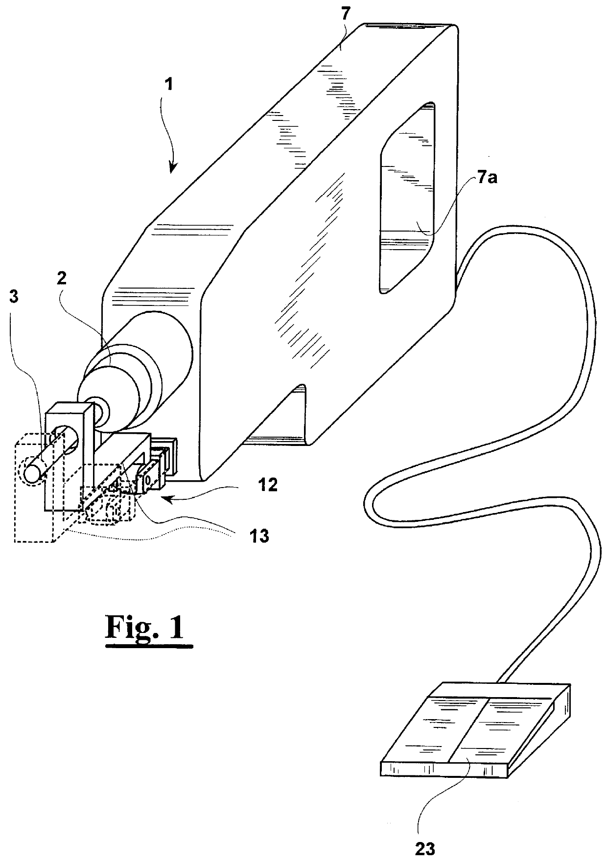
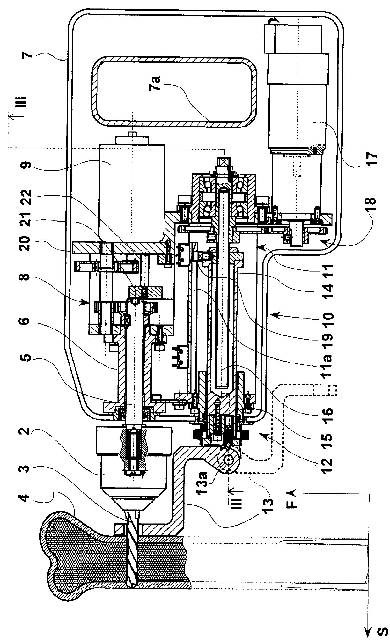
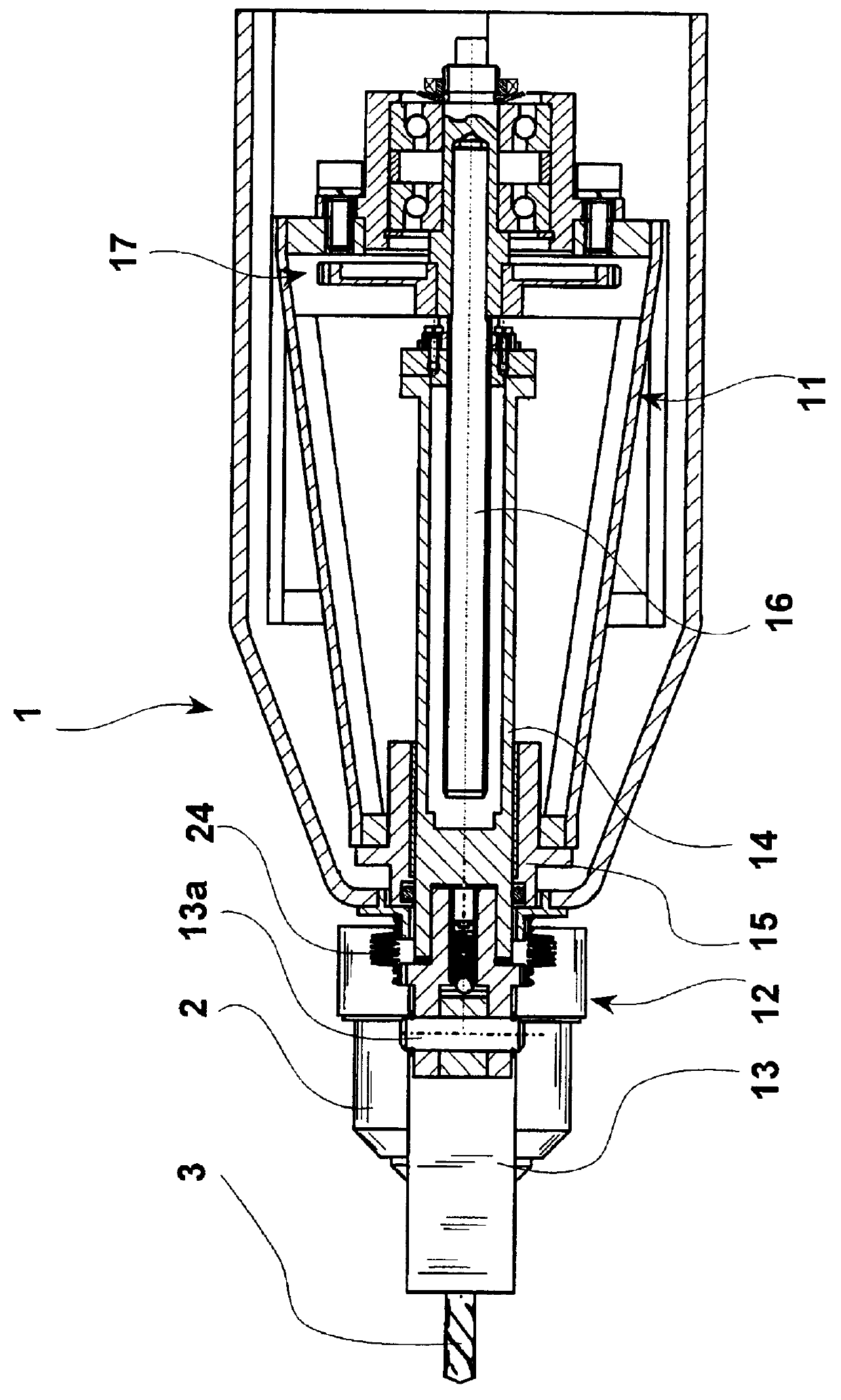
With reference to FIGS. 1 to 3, a surgical drill 1 comprises a rotating head 2 having a drill bit 3 suitable to bore a body 4 (FIG. 2), such as a body bone, during a surgical operation of osteosynthesis. Head 2 (FIGS. 2 and 3) is pivotally connected by means of a shaft 5 to a housing 6 mounted in a casing 7 having a handgrip 7a to hold the drill 1. With housing 6 engages also a gearing 8 which rotates shaft 5 operated by a motor 9.

Always with reference to FIGS. 2 and 3, to casing 7 is connected also an actuating unit 10 suitable to guide drill bit 3 with respect to body 4. More precisely, actuating unit 10 comprises a first support 11, integral to housing 6, and a second support 12 capable of resting on body 4. Second support 12 comprises a rest element 13 and a nut screw element 14 which can slide in a bushing 15 integral to casing 7 and to first support 11. With nut screw element 14 engages a screw threaded shaft 16 pivotally connected to first support 11 and brought into rotation...


PUM


Abstract

PCT No. PCT / EP97 / 06020 Sec. 371 Date Apr. 30, 1999 Sec. 102(e) Date Apr. 30, 1999 PCT Filed Oct. 31, 1997 PCT Pub. No. WO98 / 18390 PCT Pub. Date May 7, 1998A surgical drill (1), comprising a rotating head (2) having a drill bit (3) suitable to bore a body (4) and support means (7) to which the head (2) is pivotally connected. An actuating unit (10) of the movement of the drill bit (3) with respect to the body to bore (4) is provided for, comprising a first support (11) comprising the head (2) and a second support (12), suitable for resting directly upon the body (4) and translating with respect to the first support (11) parallel to the drill bit (3). The movement between drill bit (3) and body (4) is caused by the relative movement between drill bit (3) and second support (12). Means (21) for the detection of the force acting on the drill bit and means for the control of the drill bit displacement in function of the drilling force are provided for. The drill, manually holdable, presents both a reference with respect to the patient body and allows a precise control of the drill bit displacement.

Description

DESCRIPTION1. Field of the inventionThe present invention generally relates to the field of apparatus for orthopaedic surgery and, more precisely, it relates to a surgical drill and actuating unit with drill bit penetration control and breakthrough detection.2. Description of the prior artIt is at present felt by surgeons the need of a drill having sensors which can control the drill bit penetration while making a bore in a tissue, in particular a bone wall.In fact, a surgical drill is often used for osteosynthesis operations and is guided manually by the surgeon, who carries out the drilling step according to his / her experience. For example, when transversally drilling a bone, the surgeon often has either to bore both the two cortical bone walls, making a substantially through hole, or has to bore only one wall, either passing through or not passing through the trabecular or medullar bone. However, it is difficult to carry out a correct drilling step without an automatic control of...

Claims


Application Information

Patent Timeline
Patent Type & Authority Patents(United States)
IPC IPC(8): A61B17/16B23Q5/32B23Q5/22B25F5/00A61B19/00
CPCA61B17/1622B23Q5/32B25F5/003A61B2019/303A61B2090/033
Inventor ALLOTTA, BENEDETTO
Owner SCUOLA SUPERIORE DI STUDI UNIVERSITARI E DI PERFEZIONAMENTO SANTANNA
Why Eureka
Try Eureka