
Surgical drill templates and methods of manufacturing the same

a drill template and template technology, applied in the field of surgical drill template manufacturing, can solve the problems of consuming work steps, affecting the accuracy of drilling, and requiring the use of costly metal guiding sleeves in drilling holes, so as to achieve the effect of reducing costs and increasing precision

Active Publication Date: 2010-10-07
STRAUMANN HLDG AG
View PDF11 Cites 30 Cited by
  • Summary
  • Abstract
  • Description
  • Claims
  • Application Information

AI Technical Summary

Benefits of technology

The present invention provides a drill template with increased precision and reduced costs. The drill template comprises a base body made by casting or rapid prototyping, at least one reinforced portion made by casting or rapid prototyping, and at least one guiding hole within the reinforced portion made by drilling or milling. The drill template may also include reference points made by casting or rapid prototyping, guiding tubes, and pre-existing surgical templates that can be modified. The method of manufacturing the drill template involves forming a base body, adding at least one reinforced portion, and optionally adding guiding tubes or reference points. The rapid prototyping techniques used include stereolithography, selective laser sintering, laminated object manufacturing, fused deposition modeling, solid ground curing, ink jet printing, and three-dimensional printing. The method may also involve using a 3D image of a patient or correlated use of imaging techniques.

Problems solved by technology

Although these drill templates are made with great accuracy they still have several drawbacks which are not resolved by the state of the art.
In fact, the manufacturing of the drill templates carried out by means of CAD / CAM methods is complicated and entails time consuming work steps, and is therefore expensive.
On the other hand, if the drill templates are manufactured by way of rapid prototyping, costly metal guiding tubes (guiding sleeves) must be used in the guiding holes.
Moreover, the drill templates made by rapid prototyping can deform during the curing and / or drying process thereof which results in a loss of accuracy of the precise structures.

Method used


Image

  • Surgical drill templates and methods of manufacturing the same
  • Surgical drill templates and methods of manufacturing the same
  • Surgical drill templates and methods of manufacturing the same

Examples


Embodiment Construction

A) Surgical Drill Templates According to the Invention

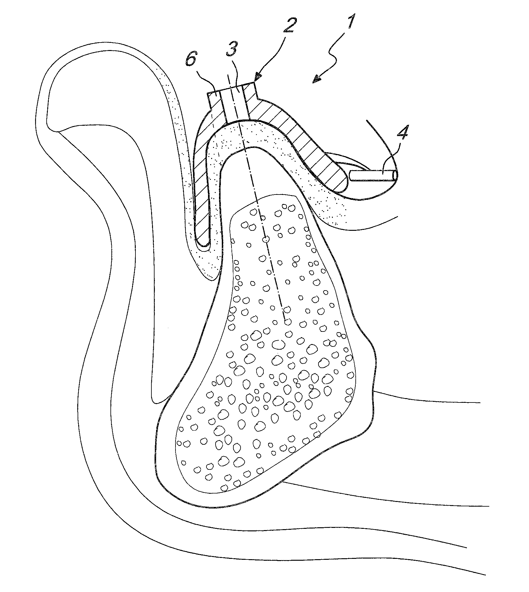
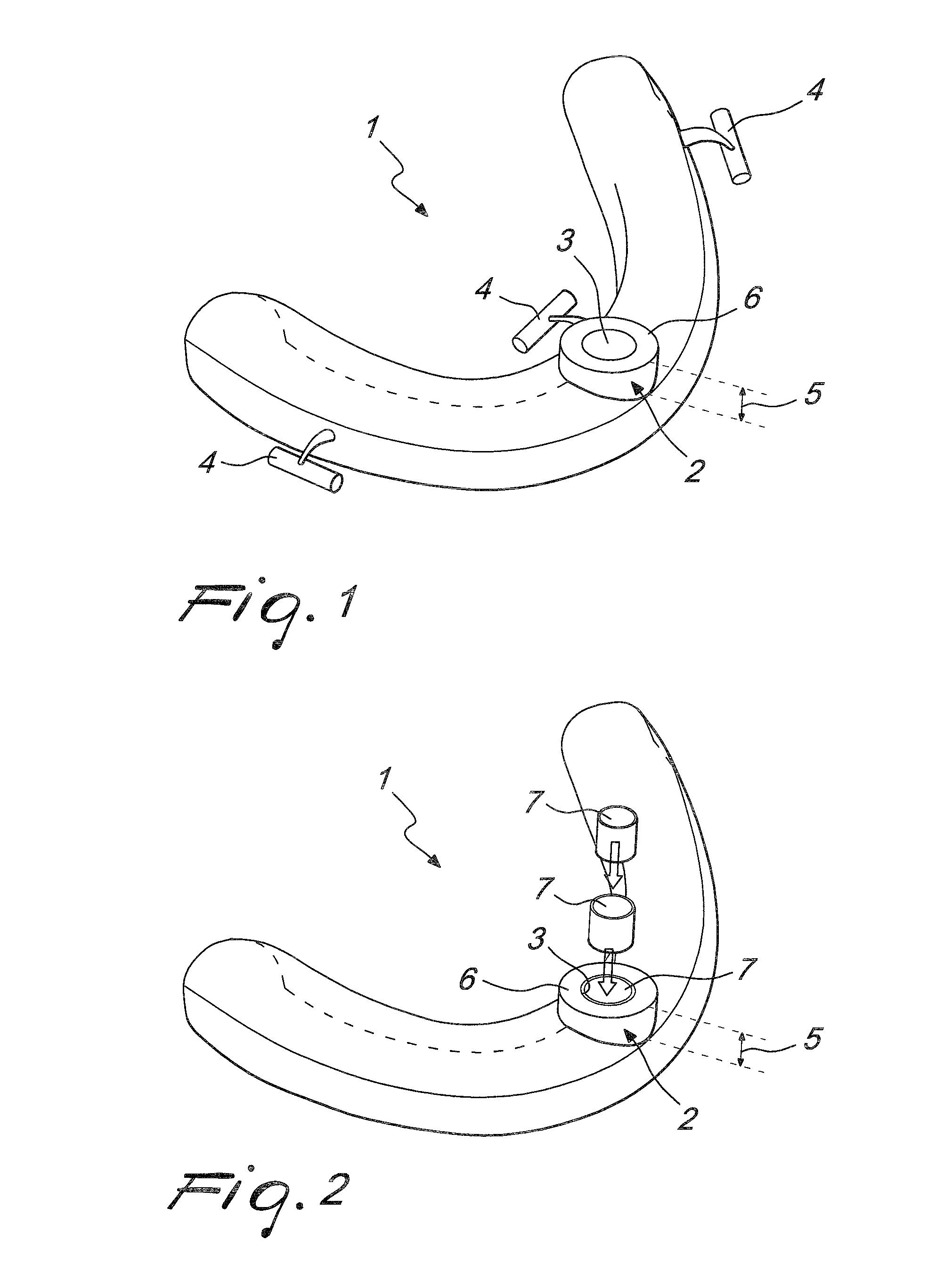
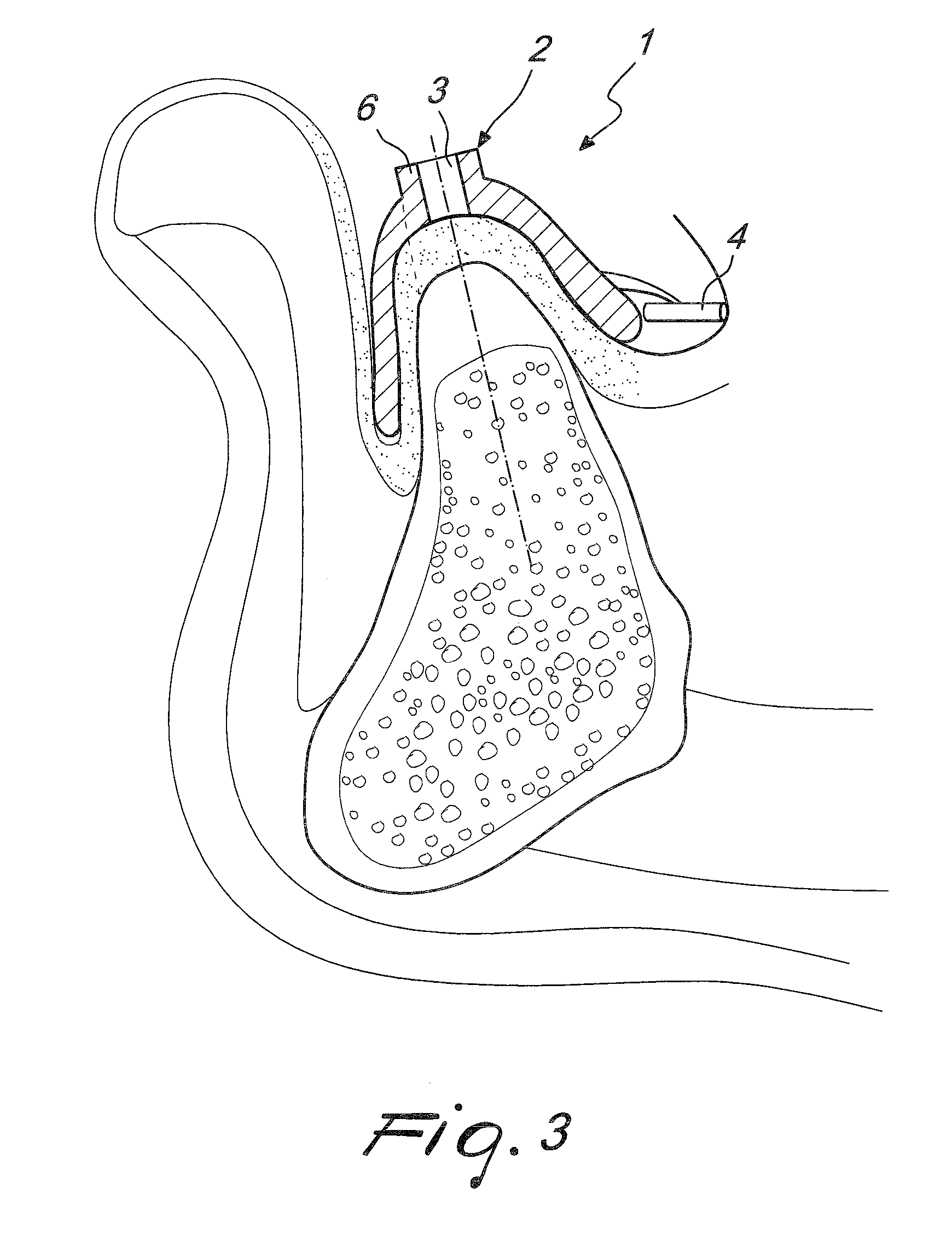
[0032]Referring to FIG. 1, a schematic representation of a drill template according to the invention is shown. The drill template has a base body (1) which can be made by casting or rapid prototyping techniques or similar. The base body (1) has one reinforced portion (2). Likewise, the reinforced portion (2) can be made by casting or rapid prototyping techniques. Moreover, one guiding hole (3) is shown within the reinforced portion (2). The guiding hole (3) can be made by drilling or milling techniques.

[0033]When the guiding hole is already incorporated in a template according to the state of the art, previously manufactured by rapid prototyping, such guiding hole can be made even and precise by drilling or milling according to the present invention.

[0034]The base body (1) and the reinforced portion (2) can be made of the same material or different materials.

[0035]In a preferred embodiment of the present invention, the same mater...


PUM

PropertyMeasurementUnit
specific heightaaaaaaaaaa
thicknessaaaaaaaaaa
depthaaaaaaaaaa

Abstract

The present invention concerns a drill template, comprising: a base body made by casting or rapid prototyping; at least one reinforced portion made by casting or rapid prototyping; and at least one guiding hole within the at least one reinforced portion made by drilling or milling. furthermore, the present invention concerns a method of manufacturing a drill template, comprising the steps of: forming a base body by casting or rapid prototyping; forming at least one reinforced portion by casting or rapid prototyping; and forming at least one guiding hole within the at least one reinforced portion by drilling or milling.

Description

BACKGROUND OF THE INVENTION[0001]The present invention relates in general to devices for dental practices, in particular to surgical drill templates used for drilling a jaw-bone for dental implant prostheses and to methods of manufacturing these drill templates.[0002]The drilling of a jaw-bone (mandibular or maxillary) for implanting a dental prosthesis represents a delicate surgical intervention. Precision in performing the drilling of the bone according to a selected position, depth and orientation is of extraordinary importance for a satisfactory prosthetical result.[0003]It is a consolidated practice to carry out the drilling by means of a custom-made surgical drill template which provides for the maintenance of predetermined parameters, such as geometrical location and depth of the hole and constant angle of the drilling axis. For this purpose the drill templates are provided with guiding holes having guiding tubes. Surgical drill templates have three basic designs: tooth-suppo...

Claims


Application Information

Patent Timeline
Patent Type & Authority Applications(United States)
IPC IPC(8): A61C8/00A61C19/00
CPCY10T29/49567A61C1/084B33Y80/00
Inventor TAORMINA, MATTEO
Owner STRAUMANN HLDG AG
Learn More