Surgical Drill Guide With Awl and Method of Use

a drill guide and surgical technology, applied in the field of drill guides, can solve the problems of limited number of anchors, difficult to run a wire through the bore, and inability to achieve precise placement over long distances, and selectively position much of the structure

Inactive Publication Date: 2010-12-09
QUANTUM SURGICAL
View PDF6 Cites 35 Cited by
  • Summary
  • Abstract
  • Description
  • Claims
  • Application Information

AI Technical Summary

Benefits of technology

[0010]It is a present object of at least some embodiments of the present invention to provide an improved drill guide, drill, and receiving awl which connect in an intraosseous location to facilitate making bone tunnels or passing sutures through bone in a minimally invasive, arthroscopic fashion.
[0013]It is another object of many embodiments of the present invention to provide a drill guide in which multiple axes of adjustability are provided which can increase a drill guide's generalization to more than one anatomic situation.
[0019]The guide may then be removed from the patient and the sleeve precisely aligned with or relative to the pin and then reinstalled in the desired configuration. Once again, the use of the actuator may assist in releasing the articulated column from a rigid configuration to a malleable and / or released configuration. Upon achieving the desired position, the actuator can be operated to lock the articulating column in a rigid configuration. Upon relocking the actuator, the sleeve can be precisely aligned and / or positioned relative to the pin. The rigid guide can then be installed relative to the patient with minimal, if any, torque on the connecting structure between the pin and the sleeve.
[0020]By providing an ability to adjust the position of the sleeve relative to the pin, precise placement over long distances may be more easily performed for some embodiments. Furthermore, an ability to selectively position much of the structure between the pin and sleeve can now be achieved, particularly when utilizing an articulated column embodiment. The connecting structure may be moved out of the way in at least some embodiments so that it does not obstruct other instrumentation, equipment and / or the line of sight of the surgeon when in use.

Problems solved by technology

The angle between the drill guide targeting tip and the drill sleeve must generally be greater than 90 degrees, which is not possible in certain location due to anatomic constraints.
Thus, when a pin is placed at a desired position relative to the bone, and after the bore is drilled, there is no easy way to run a wire through the bore in the bone so as to use to re-attach tendons or for other purposes.
While an anchor could be inserted into the bore, typically only a limited number of anchors can be used at a single location in a patient.
The bone surrounding anchors may become less strong, and the possibility of drilling one anchor into another would appear to cause problems for a patient.
Also, anchors are expensive and may not be reimbursed by all private insurance companies or government backed programs.
However, flexible drill bits are believed to be somewhat problematic in that they may not hit the intended target reproducibly due to scything.
Furthermore, a flexible bit may break off within the bone also creating issues which need to be resolved by the surgeon.
Furthermore, the applicant has discovered using many of these prior art devices which are often being applied to more sophisticated techniques in different body parts, that when the pin is placed at a desired position relative to the bone, upon attempting to locate the drill guide sleeve relative to the pin, the connecting structure between the pin and the drill guide often creates resistance or torque.
This can create problems or at least issues in at least some procedures.
As a result of these issues, some medical procedures rely on freehanding pins orthoscopically by trial and error to achieve acceptable pin placement.

Method used


Image

  • Surgical Drill Guide With Awl and Method of Use
  • Surgical Drill Guide With Awl and Method of Use
  • Surgical Drill Guide With Awl and Method of Use

Examples


Embodiment Construction

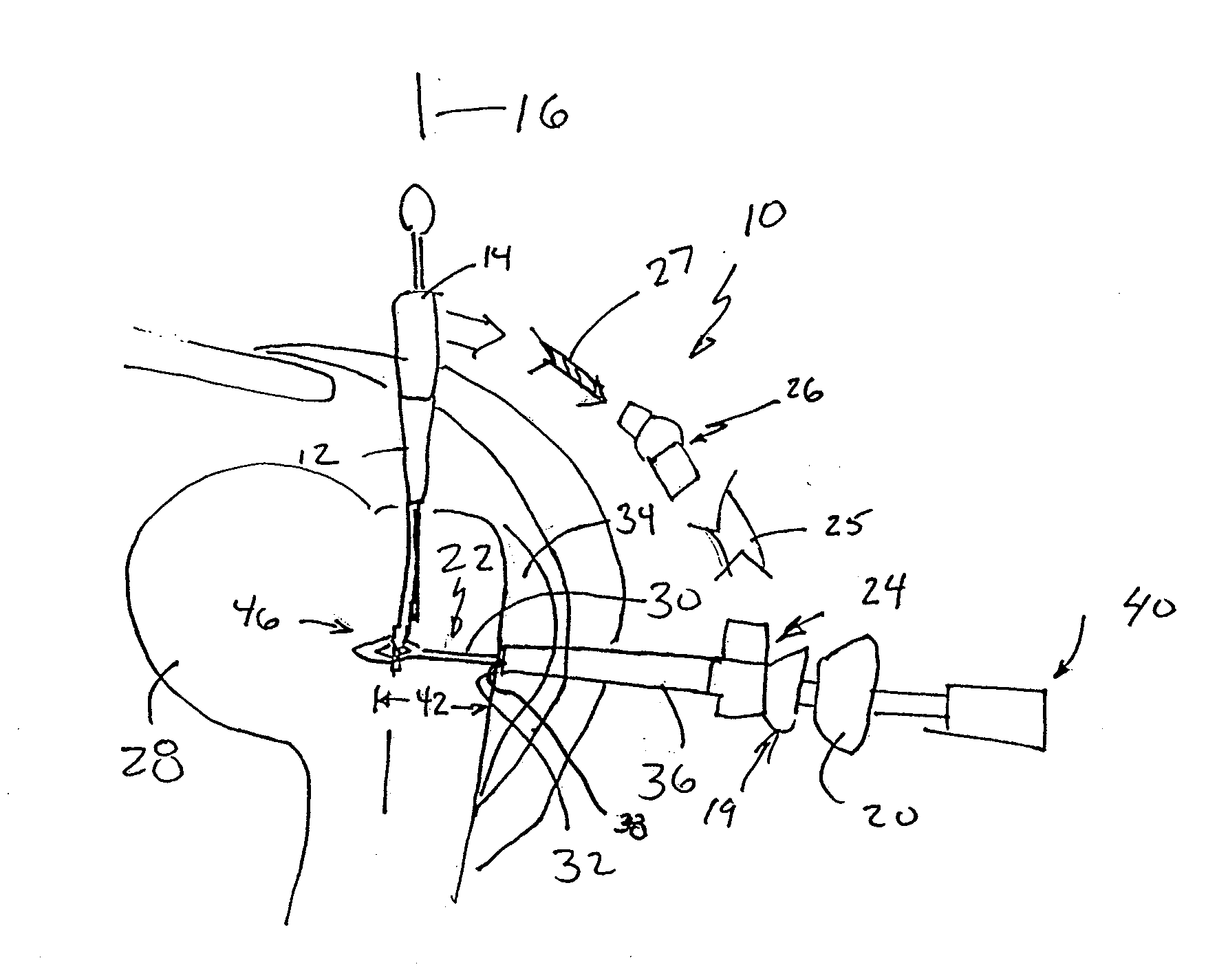
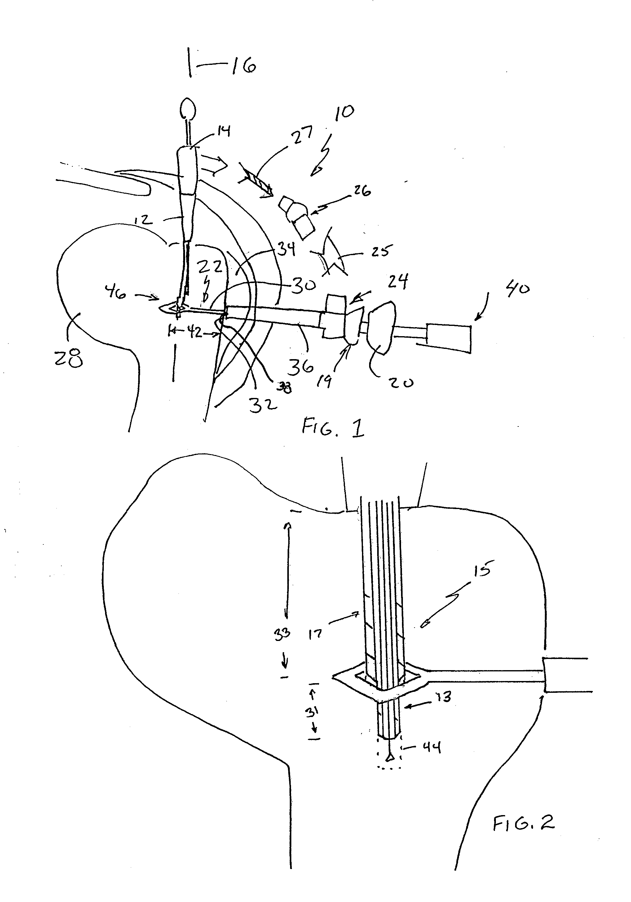
[0039]FIG. 1 shows a drill guide 10 of a presently preferred embodiment of the present invention. The drill guide 10 has a sleeve 12 received in sleeve housing 14. Sleeve 12 may be directed along sleeve axis 16 such as with an indexing or insertion mechanism 18 possibly including an electrical drill or other appropriate device such as a cannulated awl. U.S. Pat. No. 5,458,602, incorporated by reference, shows one style of housing 14 and sleeve 12, but there are certainly others as would be known by those of ordinary skill in the art that would work satisfactorily.

[0040]Pin 22 is shown connected to arm portion 24. Various arm portions 25,26,27 are shown with broken lines such as an articulated column arm portion 26. Further detail regarding an articulated column arm portion is discussed below. Configurations such as a flexible or otherwise movable wire 27 or other connection, or rigid, i.e. non-movable arm 25 to connect pin 22 to drill 15 and / or sleeve 12 may also be utilized. Any or...


PUM


Abstract

A drill guide and pin system is provided whereby a drill may be inserted through a drill sleeve into a bone portion to provide a drill bore. For some embodiments, a cooperating pin provides a pin bore which intersects the drill bore at a predetermined angle α and predetermined location relative to at least one of the drill sleeve and / or bore. The pin may have an integral catch so that when a wire is inserted through the drill bore, the catch can pull the wire through the pin bore for use in various surgical techniques. Some embodiments have an articulated arm which can lock in a fixed position in a fixed configuration and have a moveable configuration as well.

Description

CLAIM OF PRIORITY[0001]This application claims the benefit of U.S. Provisional Patent Application No. 61 / 184,031 filed Jun. 4, 2009 and U.S. Provisional Patent Application No. 61 / 184,360 filed Jun. 5, 2009.FIELD OF THE INVENTION[0002]The present invention relates to drill guides utilized in surgery, and more particularly to drill guides for creation of bone tunnels, and for at least some embodiments to drill guides having a catch configured to capture a wire inserted through a first bore made with a drill which allows for a surgeon or other medical personnel to run a wire through a portion of bone through the first bore and out a second bore left by retraction of the pin out of the bone and / or for at least some embodiments drill guides having at least one adjustable arm such as an articulated column which allows for a surgeon or other medical personnel to adjust the position of a pin relative to a drill guide sleeve in an efficient and easy manner, such as around non-linear anatomic...

Claims


Application Information

Patent Timeline
Patent Type & Authority Applications(United States)
IPC IPC(8): A61B17/15A61B17/90
CPCA61B17/1684A61B17/1697A61B17/1796A61B17/8861A61B17/1778
Inventor SANDERS, BRETT
Owner QUANTUM SURGICAL
Why Eureka
Try Eureka