surgical drill aimer

Inactive Publication Date: 2011-07-07
UNIVERSITY OF CAPE TOWN +1
View PDF2 Cites 33 Cited by
  • Summary
  • Abstract
  • Description
  • Claims
  • Application Information

AI Technical Summary

Benefits of technology

[0011]Yet further features of the invention provide for a suture passage to be configured to releasably secure a suture adjacent the drill target; and for the suture passage to include a pair of surfaces biased towards

Problems solved by technology

Performing PCL reconstructive surgery arthroscopically requires specialised skills as it is greatly complicated by the poor visibility at the tibial insertion of the PCL.
A suture must be passed through this point but this is very difficult to achieve as the tip of the suture cannot be visualized due to the poor visib

Method used


Image

  •  surgical drill aimer
  •  surgical drill aimer
  •  surgical drill aimer

Examples


Embodiment Construction

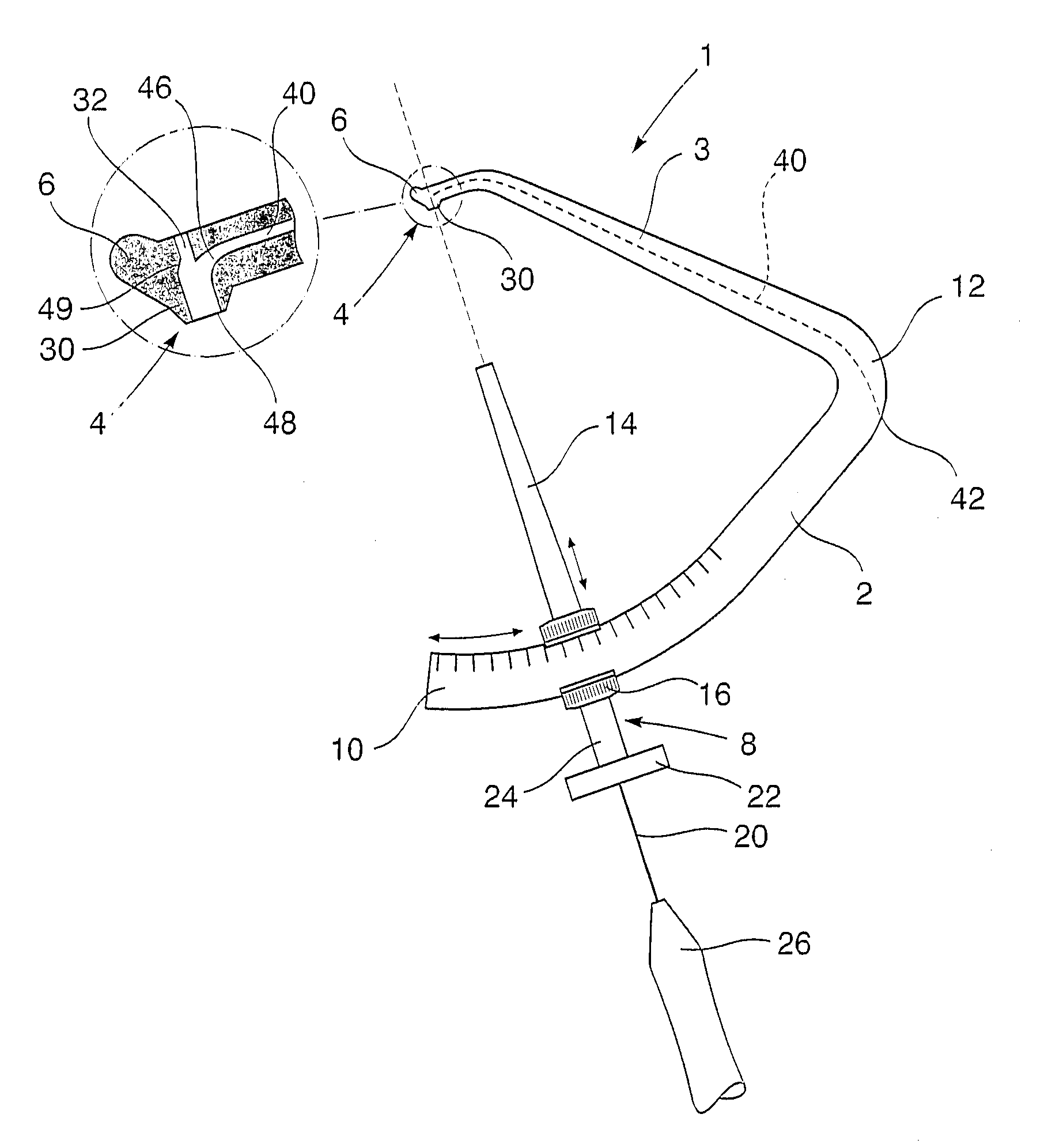
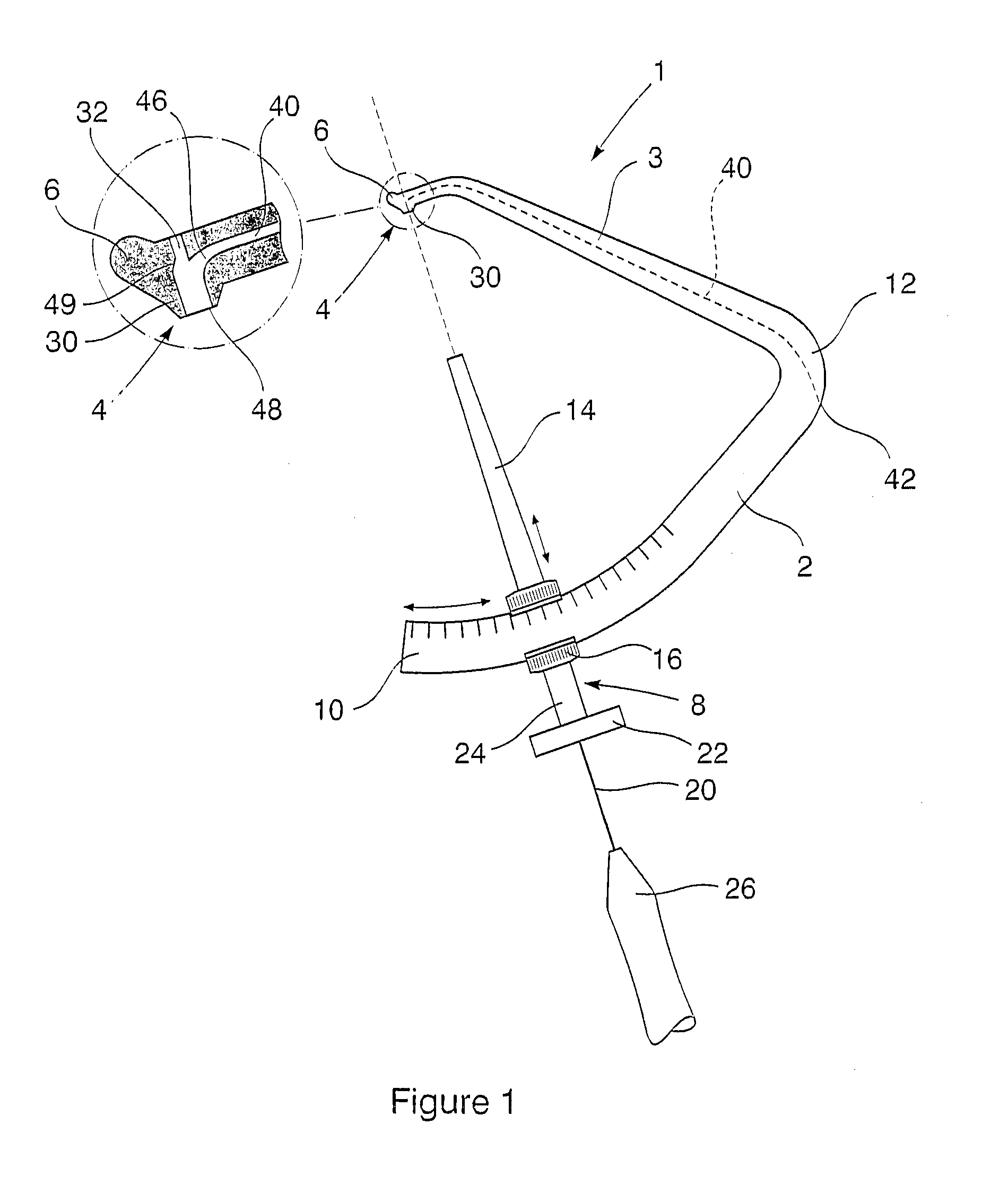
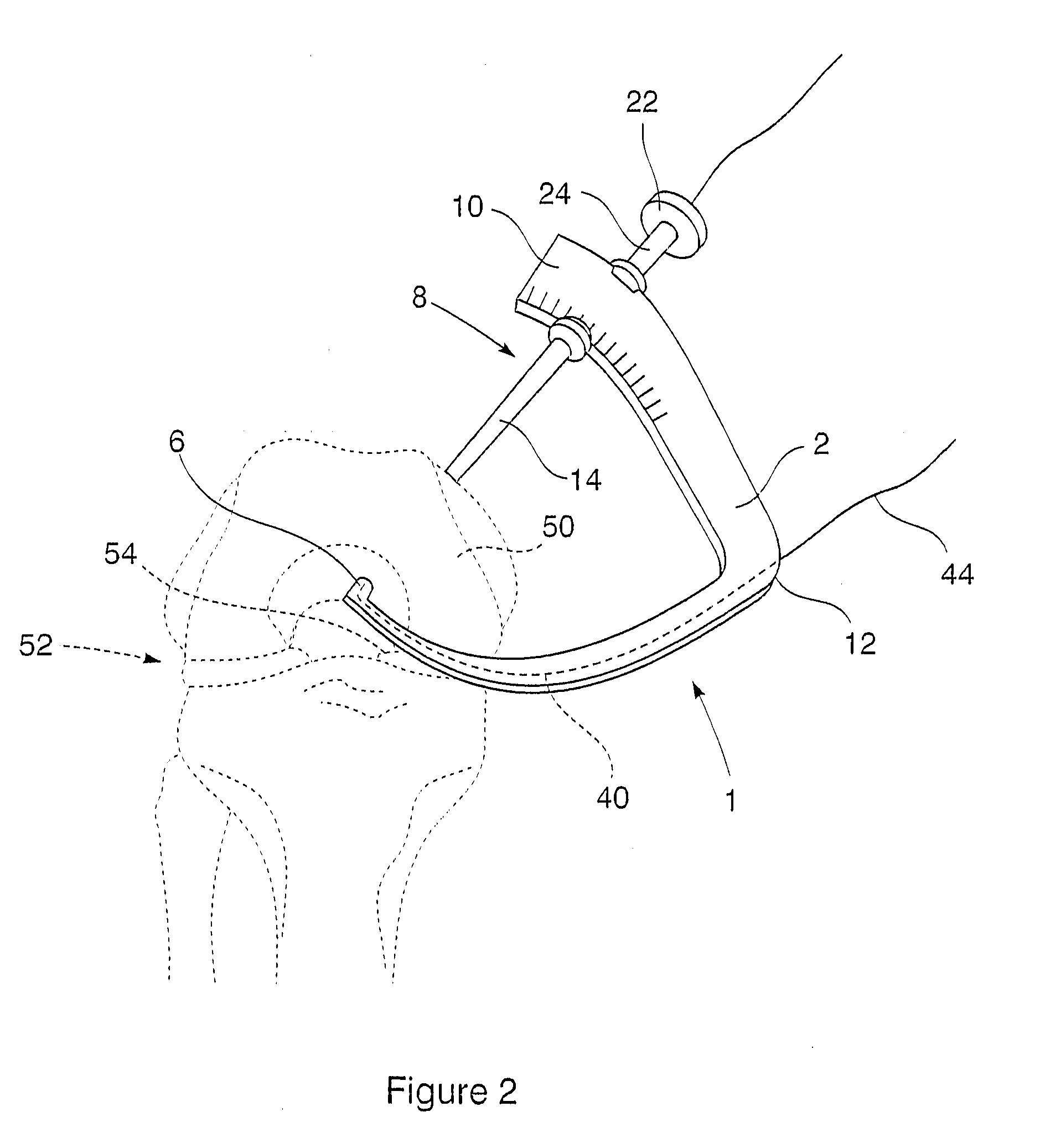
[0018]In the embodiment of the invention illustrated in FIGS. 1 and 2, a drill aimer (1) includes a first arm (2) and a second arm (3) joined at one end to form a generally V-shaped arm assembly. The second arm (3) has a drill target (4) at its free end (6) and the first arm carries a drill guide (8) towards its free end (10). The second arm (3) tapers from the bend or junction (12) towards the drill target (4) and is also slightly curved towards the free end (6). The first arm (2), on the other hand has a substantially constant width from the apex (12) towards its free end (10).

[0019]The drill guide (8) includes an elongate drill sleeve (14) which is slideably secured in a carriage (16) which is in turn adjustably secured to the first arm (2) in a region thereof that is arcuate so that the axis of the drill sleeve remains directed towards the drill target through a range of different positions. The sleeve (14) is shaped to receive a drill bit (20) therethrough and has a flange (22)...


PUM


Abstract

A surgical drill aimer (1, 70, 100) is provided that is configured to be secured about a bone with a drill guide (8, 82, 108) on one side and a drill target (4, 88, 114) on an opposite side. A suture passage (40, 92, 120) is provided which is shaped to receive a suture (44, 94, 130) and has an exit (46, 90, 12) at or near the drill target and configured such that a suture extending therefrom is accessible through a drill hole formed using the drill aimer and opening in line with the drill target.

Description

FIELD OF THE INVENTION[0001]This invention relates to a surgical drill aimer, more particularly, but not exclusively, to a drill aimer for use in arthroscopic surgery.BACKGROUND TO THE INVENTION[0002]Arthroscopic surgery is often the preferred surgical procedure for the treatment of many different injuries such as knee injuries, an example of which is the reconstruction of the posterior cruciate ligament (PCL). During arthroscopic surgery such as PCL reconstructive surgery, a drill aimer, also referred to as a drill guide or drill jig, is often used to facilitate precise formation of a drill hole through a bone. These devices may include a pair of arms or jaws, each operatively located on opposite sides of the bone. One arm carries a guide, typically a sleeve or tube, for the drill and the end of the other carries a bone contacting surface. This contacting surface acts as the target for the drill and typically has a central aperture through which the drill tip projects on exiting th...

Claims


Application Information

Patent Timeline
IPC IPC(8): A61B17/56
CPCA61B17/06166A61B17/1764A61B17/1714
Inventor VAN DER MERWE, WILLEM MAREWILSON, DAVID ALEXANDER JAMES
Owner UNIVERSITY OF CAPE TOWN
Why Eureka
Try Eureka