Drill having radially overlapping indexable cutting inserts

Inactive Publication Date: 2000-03-21
SECO TOOLS AB
View PDF5 Cites 82 Cited by
  • Summary
  • Abstract
  • Description
  • Claims
  • Application Information

AI Technical Summary

Problems solved by technology

This means that the cutting insert actually only can give two n

Method used


Image

  • Drill having radially overlapping indexable cutting inserts
  • Drill having radially overlapping indexable cutting inserts
  • Drill having radially overlapping indexable cutting inserts

Examples


Embodiment Construction

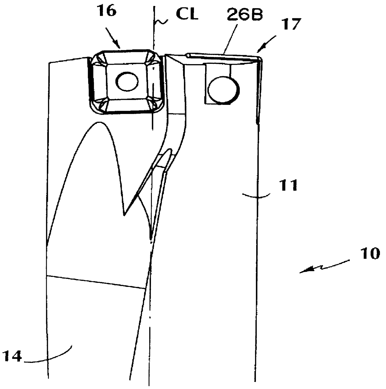
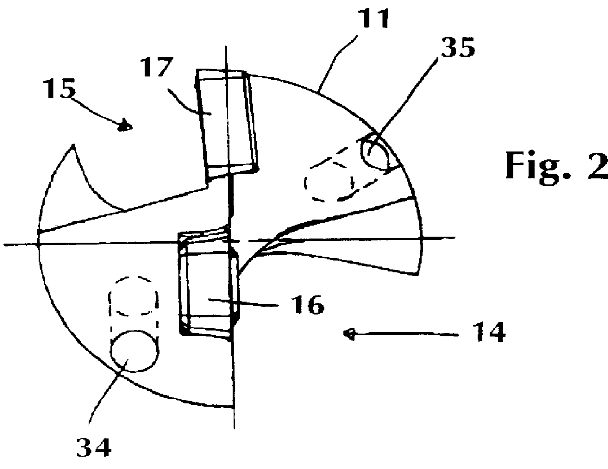
FIGS. 1 and 2 show a cylindrical drill shank 11 that is provided with two insert pockets at its forward end, the insert pockets located on respective sides of the center line CL (axis of rotation) of the drill. Helical recesses or chip flutes 14, 15 are provided for chip transport. Both insert pockets are provided with central holes for receiving locking screws (not shown) for clamping cutting inserts in the pockets in a known manner. The pockets comprise a central pocket which is provided radially inside the periphery of the drill shank 11, and a peripheral pocket which terminates in the outer cylindrical periphery of the drill shank. The insert pockets are designed in the drill shank 11 in a manner such that they possess different axial clearance angles and, together with the cutting inserts, achieve full drilling of the entire hole diameter.

Each cutting insert pocket comprises a tangential support surface, an axial support surface as well as a radial support surface. The support ...


PUM

PropertyMeasurementUnit
Angleaaaaaaaaaa
Diameteraaaaaaaaaa

Abstract

A drill includes a shank, a central insert and a peripheral insert. The shank defines a central axis of rotation and has pockets which carry the peripheral and central inserts. Chip flutes are formed in an outer periphery of the shank for conducting chips cut by the respective inserts. The peripheral insert includes a first operative cutting edge, and the central insert includes a second operative cutting edge which overlaps the first cutting edge at an overlap region. The central insert forms a rake surface adjacent to the second cutting edge. The rake surface includes a first portion disposed at the overlap region, and a second portion disposed at the axis of rotation of the shank. The first portion has a larger rake angle than the second portion.

Description

The present invention relates to a drill for drilling metallic workpieces, as well as a cutting insert to be used in connection with the drill.PRIOR ARTIn a known drill of the above-mentioned type the drill has square indexable inserts, namely, a central insert and a peripheral insert of identical design. The central insert overlaps the axis of rotation of the drill and the peripheral insert overlaps the central insert. Each corner portion of the central insert comprises a chamfer which in the operative (cutting) position of the insert is arranged to overlap the rotational axis. After indexing of the central insert that same chamfer gets relocated to another position which may still constitute an operative position, whereby the cutting insert does not cut as light as a new cutting insert. This means that the cutting insert actually only can give two non-worn cutting edges per cutting insert, which is uneconomical.OBJECTS OF THE PRESENT INVENTIONOne object of the present invention is...

Claims


Application Information

Patent Timeline
IPC IPC(8): B23B27/14B23B51/04B23B51/00
CPCB23B27/141B23B51/0493Y10T408/906Y10T407/23Y10T408/868Y10S408/713B23B2251/50B23B51/02B23B2251/408B23B2251/204B23B2251/04
Inventor LAMBERG, FREDRIK
Owner SECO TOOLS AB
Why Eureka
Try Eureka