Practical structure for making a multilevel converter

a converter and multi-level technology, applied in the direction of dc-ac conversion without reversal, process and machine control, instruments, etc., can solve the problem that the structure implementation does not meet expectations

Inactive Publication Date: 2000-03-21
APC POWER CONVERSION
View PDF4 Cites 12 Cited by
  • Summary
  • Abstract
  • Description
  • Claims
  • Application Information

AI Technical Summary

Benefits of technology

In this way, the module in question contains a capacitive element connected to each of its pairs of poles and not only a cell capacitor connected to the downstream pair of poles, thereby pr

Problems solved by technology

Unfortunately, experience has shown that such stru

Method used


Image

  • Practical structure for making a multilevel converter
  • Practical structure for making a multilevel converter
  • Practical structure for making a multilevel converter

Examples


Embodiment Construction

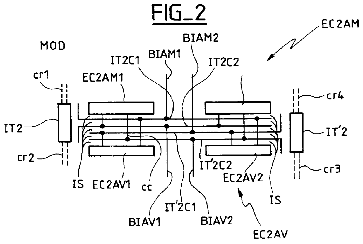
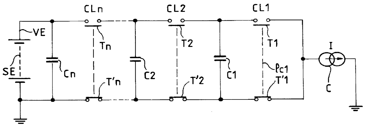
No further reference is made to the electrical description of the multilevel converter shown in FIG. 1, except to mention that a conventional structural implementation of it would comprise identical units, each of which corresponds to one cell of the converter, and thus each of which contains two switches and one cell capacitor, e.g. the switches T2 and T'2 and the capacitor C2. The capacitor C1 would thus belong to a preceding cell. The connections between the upstream poles of the switches T2 and T'T and the downstream poles of the switches T1 and T'1 would thus be connections between modular units, which connections would be relatively long and therefore relatively inductive.

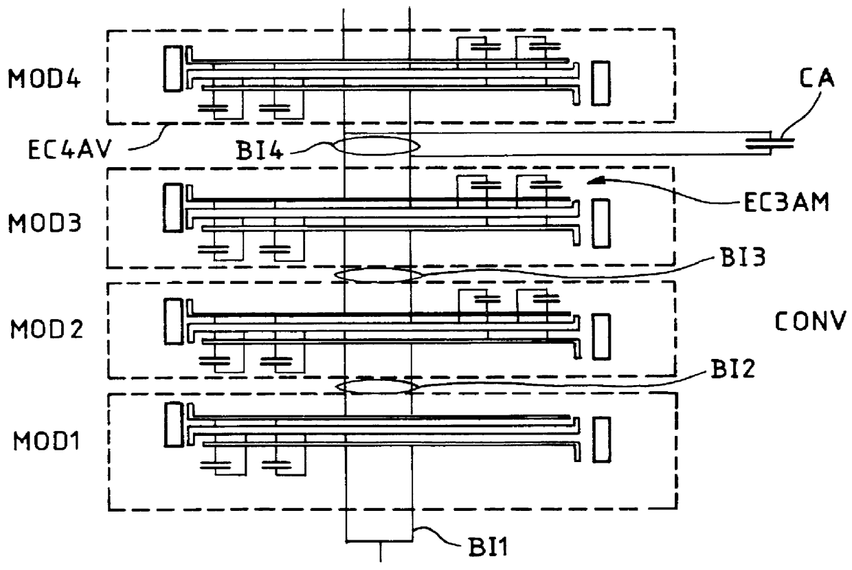
As explained below, the invention consists not only in limiting the inductive nature of the connections but also in making sure that, physically, a capacitive element is connected to the upstream poles of the switches of each cell, so that they are protected from the effects of the inductance of the conductor...


PUM


Abstract

A multilevel converter structure made up of cells in cascade, each intermediate cell containing two switches, with one pole of each of the two switches forming part of a pair of upstream poles and the other pole of each of the switches forming part of a pair of downstream poles, the pair of downstream poles of an upstream cell being connected to the pair of upstream poles of a downstream cell, the converter structure also having a respective capacitor for each cell, each capacitor being connected between the two poles constituting the pair of downstream poles of its cell. The converter structure is made up of modules, among which at least an intermediate module contains an upstream capacitor element, in addition to two switches corresponding to the switches of an intermediate cell, the capacitance of said capacitor element being a fraction of the capacitance of the cell capacitor of said upstream cell, while a module upstream from said intermediate module contains a downstream capacitor element whose capacitance is a second fraction of the capacitance of the cell capacitor of said upstream cell.

Description

The converter described in that patent application is shown, by way of example, in accompanying FIG. 1. It essentially comprises, between a voltage source SE and a current source C, a succession of controllable switching cells CL1, CL2, . . . , CLn, each having two switches T1, T'1; T2, T'2; . . . ; Tn, T'n, with one pole of each of the two switches forming part of a pair of upstream poles and the other pole of each of the switches forming part of a pair of downstream poles, the pair of downstream poles of an upstream cell being connected to the pair of upstream poles of a downstream cell, and the pair of upstream poles of a first cell CL1 being connected to said current source C, while the pair of downstream poles of a last cell CLn is connected to said voltage source SE, the converter also comprising a respective capacitor C1, C2, . . . , Cn for each cell, each capacitor being connected between the two poles constituting the pair of downstream poles of its cell, the converter furt...

Claims


Application Information

Patent Timeline
IPC IPC(8): H02M7/48H02M7/483
CPCH02M7/483H02M2007/4835H02M7/4837
Inventor COURAULT, JACQUES
Owner APC POWER CONVERSION
Why Eureka
Try Eureka