Battery receiving chamber and hearing aid

a battery receiving chamber and hearing aid technology, applied in the direction of hearing aid mounting/interconnection, fuel and primary cells, electrochemical generators, etc., can solve the problems of watertight filter, insufficient oxygen supply, and difficulty in applying the above-described air cells

Inactive Publication Date: 2000-03-21
RION COMPANY
View PDF5 Cites 124 Cited by
  • Summary
  • Abstract
  • Description
  • Claims
  • Application Information

AI Technical Summary

Problems solved by technology

Therefore, it is difficult to apply above-described air cells, which need oxygen so as to generate voltages, as power supply cells for such hearing aids.
However, this type of hearing aid 20 has a problem that the waterproof filter 25 is slow-drying because, as above described, the through-hole is formed at the bottom of the knob container 21A and the knob 22 covers the waterproof filter 25 in use.
In this case, the wet waterproof filter 25 hardly passes air so that this type of hearing aid has a problem that it cannot supply sufficient oxygen to the air cell contained in the battery compartment 23A in the hearing aid itself 23.
Therefore, this type of hearing aid has a problem that external moisture easily invade from a part having weaker pinching force against the seal packing 20 among the joint part 4A of the case itself 4 and the joint part 7A of the battery cover 7.
However, it is difficult to obtain the pinching force necessary to enable the hearing aid 1 to have the waterproof characteristic for use in a swimming pool, bath compartment, and the like where the waterproof characteristic is necessary.
However, since a user of a hearing aid is usually an aged person who is clumsy, it is problem in view point of using convenience to detach the battery cover against the elastic force of the O-ring when detaching the battery cover from the case itself, if the press fit method is applied as a setting method of the battery cover of the battery receiving chamber to the case itself.
However, in the hearing aid 1 having this type of constitution, it is a problem that stress to the seal packing 23 inserted to the joint part 22 is biased when the case chassis 5 is closed.
In addition, since the hearing aid 1 has a constitution where both ends of the seal packing 23 are bent, assembling operation is difficult and shaping of the seal packing 23 itself is difficult, too.

Method used


Image

  • Battery receiving chamber and hearing aid
  • Battery receiving chamber and hearing aid
  • Battery receiving chamber and hearing aid

Examples


first embodiment

(1) First Embodiment

(1-1) Whole Constitution of a Hearing Aid

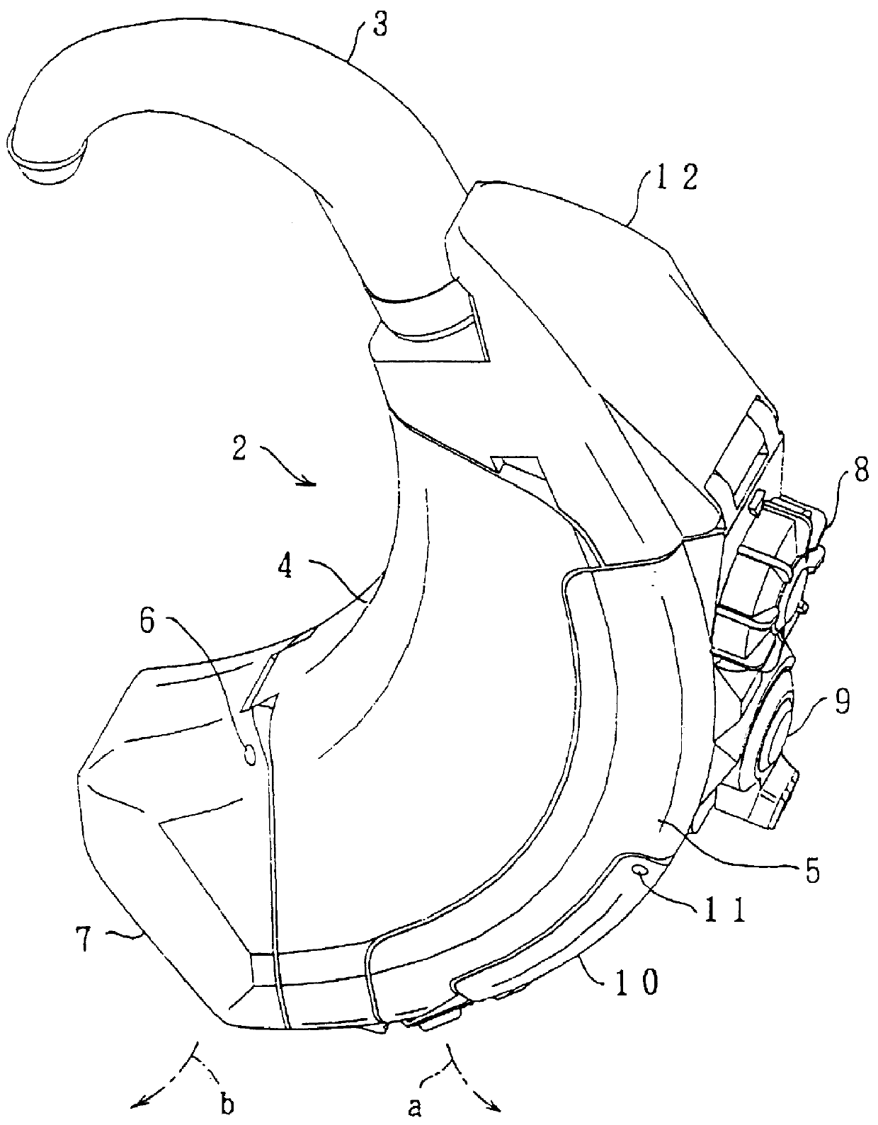
In FIGS. 6 and 7, the reference number 30 shows a waterproof externally worn hearing aid as a whole, a box-like case 31 composed with plastic resin is formed in an arch shape so as to fit to a shape of a back part of an earlobe at its end, a wind cover 32 and a hook 33 are integrally mounted.

The case 31, as is clear in FIG. 7, comprises: a case itself 40 forming an internal circumference part and a base part of the case 31; a case chassis 41 that is rotationally supported at a tip part of the case itself 40 and forms an external side face of the case 31; and a battery cover 42 blocking a cylindrical battery compartment 40A formed in a base part of the case itself 40. In addition, the case 31 is assembled as shown in FIG. 6 by screwing the case chassis 41 onto an end part of an electrode 43 protruding inside the case itself 40 and by setting the battery cover 42 like screwing into the case itself 40.

In this case, since a se...

second embodiment

(2) Second Embodiment

(2-1) Constitution of a Battery Receiving Chamber

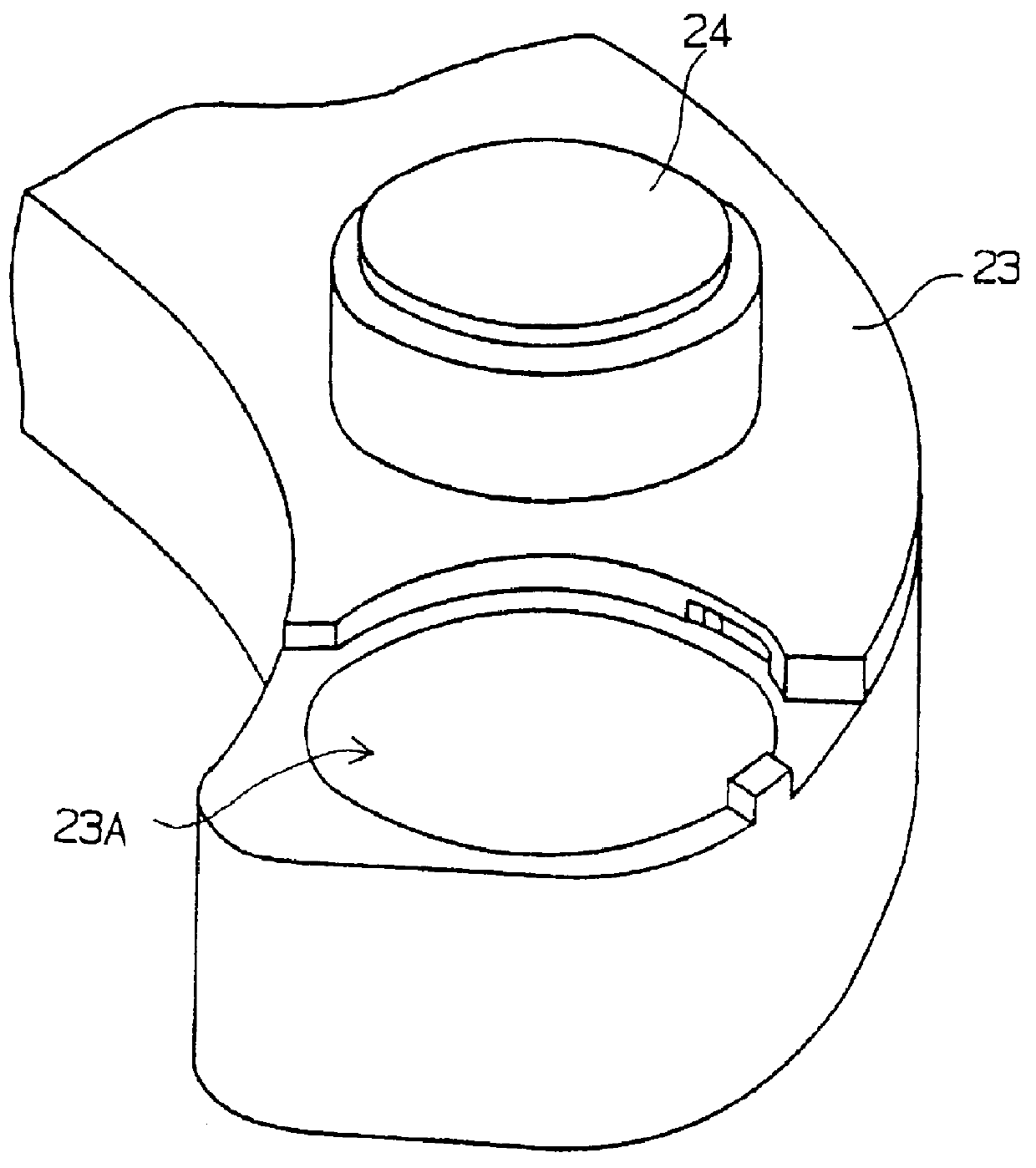
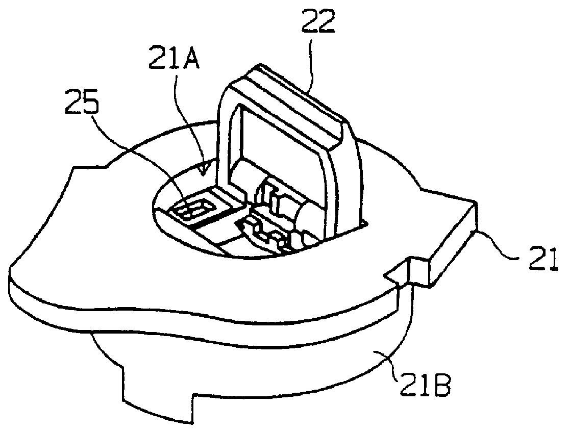
The battery cover 42 forming a part of a battery receiving chamber in this hearing aid 30, as shown in FIGS. 10 and 11, comprises the battery cover itself 71, disc-shaped waterproof filter 70, and ring-shaped filter clamp 72.

In this case, a ring-shaped convex part 71B is formed in an inside of a approximately disc-shaped base part 71A forming the external side face of the battery cover itself 71, and the above-described battery retaining walls 42A and 42B are located in the end surface of the ring-shaped convex part 71B.

In addition, a slot (not shown) is provided along circumference of the external side face of the ring-shaped convex part 71B, and the above-described O-ring 45 is embedded with this slot.

Furthermore, since the air vent 71AX communicating the outside of the case 31 with the battery compartment 40A is provided in a central part of the base part 71A surrounded with the ring-shaped convex part 71B, ext...

third embodiment

(3) Third Embodiment

(3-1) Constitution of the Case

In this embodiment, as shown in FIG. 18, the microphone 60 positioning at the end part of the case 31 is contained in the case chassis 41, although this is different from the previous embodiment. Against this, the earphone positioning at the end part of the case 31 is contained in the case itself 40 as same as in the previous embodiment. In this manner, by containing the microphone in the case chassis 41, the case chassis 41 is divided from the box-like case 31 by a plane connecting from nearly the center of the end face of the case 31 to the back rear end of the case 31, and forms the overall back face of the case 31.

Therefore, in the hearing aid 30, when the case chassis 41 is opened, parts such as the microphone 60 and earphone 62 located in the case 31 are exposed, and hence, maintenance work such as part change can be easily done.

In addition, in the hearing aid 30, by dividing the case 31 in this manner, the joint part 100 betwe...


PUM

PropertyMeasurementUnit
stressaaaaaaaaaa
heightaaaaaaaaaa
circumferenceaaaaaaaaaa

Abstract

In a battery receiving chamber, the first convex part is formed in the internal side face of the battery compartment and the second convex part which corresponds to the first convex part is formed in the battery cover, the first and second convex part respectively having the inclined faces which gradually rise toward the rotational direction in which the battery cover is detached from the battery compartment, so that a battery receiving chamber having good usage convenience and highly reliable can be realized. Further, in a hearing aid using the above, waterproof means is located so as to block the air vent formed in the battery cover, and a slot connecting the end part of battery cover and the air vent in the external side face of the battery cover is comprised, so that a hearing aid which can supply practically sufficient volume of air into the case and has high waterproof performance can be realized. Further, the case of this hearing aid is divided into two that the first half-case for receiving the earphone, and the second half-case for receiving the microphone, and the joint part between the first and second-half cases is formed so as to substantially flat, in order to apply stress without bias to the waterproof member inserted into the joint part. Thereby, a hearing aid in which the waterproof performance can be further improved can be realized.

Description

1. Field of the InventionThis invention relates to a battery receiving chamber and a hearing aid using the same, and more particularly, is suitable to a waterproof type of hearing aid.2. Description of the Related ArtHeretofore, in this type of hearing aid, a waterproof function has been attained by increasing a degree of tight-coupling between components.As this type of hearing aid, there is an ear-hung type of hearing aid 1 (Japanese Patent Publication No. 3-39440 and Japanese Utility Model Publication No. 3-6075) as shown in FIG. 1. That is, in the hearing aid 1, a hook 3 is spring-coupled to an edge part of a case 2 formed in an arched shape as a whole, and the entire hearing aid 1 can be held at a backside position of user's earlobe by hanging the hook 3 on the upper end part of user's earlobe.By attaching a tube and an ear plug (not shown) to an edge of the hook 3, the hearing aid 1 can send hearing aid sound, which is obtained from the earphone, into user's ear-hole through a...

Claims


Application Information

Patent Timeline
Patent Type & Authority Patents(United States)
IPC IPC(8): H04R25/00H01M12/06H01M12/00
CPCH04R25/602H04R25/65H01M12/06H04R25/60H04R2225/021H04R2225/61H04R25/603H04R25/607H04R25/609
Inventor NARISAWA, YOSHIYUKIARAKI, TOSHIYUKI
Owner RION COMPANY
Why Eureka
Try Eureka