

Trailer brake control device of tractor-trailer combination vehicle for suppression of side sway of trailer
- Summary
- Abstract
- Description
- Claims
- Application Information
AI Technical Summary
Benefits of technology
Problems solved by technology
Method used
Image

Examples
first embodiment
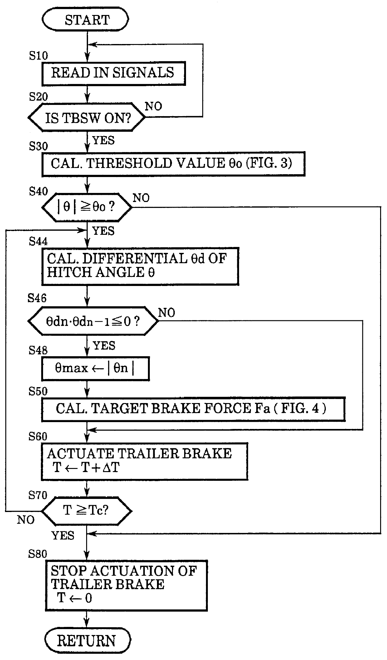
In the following, the operation of the trailer brake control according to the present invention will be described in more detail with respect to a first embodiment with reference to the flowchart shown in FIG. 2. The control routine according to such a flowchart is started upon a closure of an ignition switch not shown in the figure and executed repetitively at a predetermined cycle time as long as the ignition switch is kept closed.
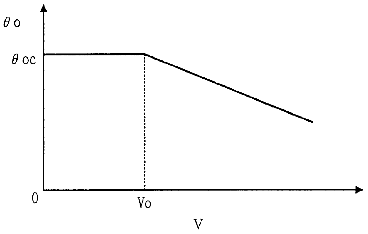
In step 10, signals are read in, and in step 20 it is judged if the trailer brake switch TBSW is on or not. If the answer is no, the control returns to step 10, withholding to execute the automatic trailer brake control according to the present invention. When the answer of step 20 is yes, the control proceeds to step 30, and a threshold value .theta. o of the hitch angle .theta. is calculated based upon the vehicle speed V by referring to a map such as shown in FIG. 3. In the shown embodiment, the threshold value .theta. o is so designed as to be a cons...
second embodiment
FIG. 7 shows a flowchart similar to that of FIG. 2, showing the present invention in the form of its operation. In FIG. 7, the steps corresponding to those shown in FIG. 2 are designated by the same step numbers.
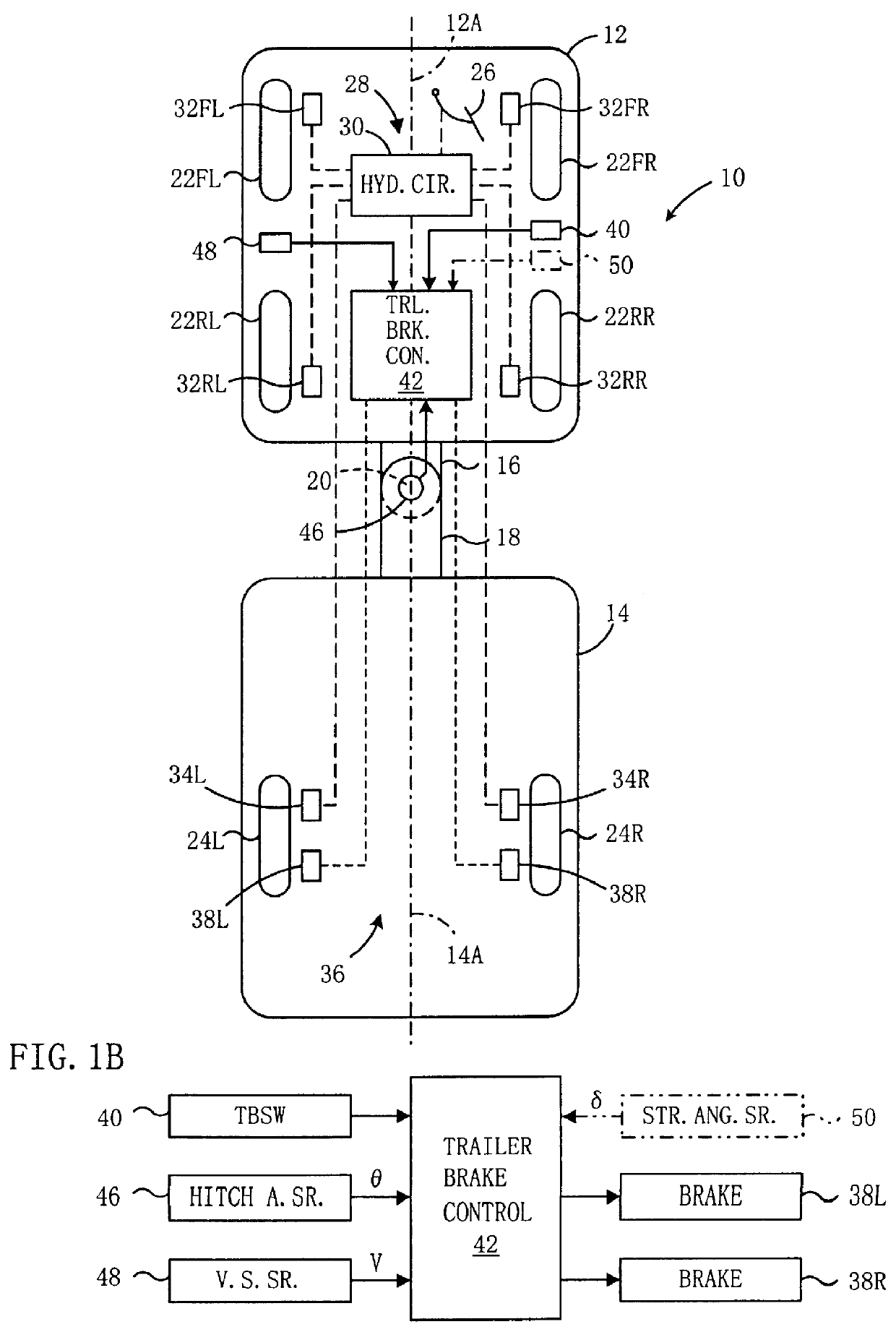
In this second embodiment, the trailer brake control device 42 is further supplied with a signal representing steering angle .delta. of the tractor from the steering angle sensor 50 shown by the phantom indication in FIG. 1B as already described, in addition to those input signals therein shown by the positive indication.
In this second embodiment, the trailer brake is also actuated when the magnitude of hitch angle .theta. increases beyond the threshold value .theta. o of the map shown in FIG. 3, so as to suppress the side swaying of the trailer. In this embodiment, however, before executing the side sway suppress control of the trailer, the necessity thereof is checked against the steering behavior of the tractor.
So in step 21, it is judged if the vehicle speed V is equal t...
third embodiment
FIG. 9 shows a flowchart similar to that of FIG. 2 or 7, showing the present invention in the form of its operation. In FIG. 9, the steps corresponding to those shown in FIG. 2 or 7 are designated by the same step numbers.
In this third embodiment, steps 10-40 are executed in the same manner as in the second embodiment shown in FIG. 7, except that steps 24 and 25 are omitted. Then, if the answer of step 40 is yes, in step 52 differential .theta. d of the hitch angle .theta. is calculated, and then in step 54 the braking duration Tc is calculated based upon the absolute value of the differential .theta. d by referring to a map such as shown in FIG. 10. In step 56, the target brake force Fa is calculated also based upon the absolute value of the differential .theta. d by referring to a map such as shown in FIG. 11. Then in steps 60 and 70, the brake means 38L and 38R are actuated according to the target brake force Fa and the braking duration Tc in the same manner as in steps 60 and 70...
PUM
 Abstract
Description
Claims
Application Information