Tandem regenerative brake control method

A technology of regenerative braking and braking control, applied in the direction of brakes, electric braking systems, electric vehicles, etc., can solve the problems of low conversion efficiency and complex structure, and achieve the effect of improving recovery efficiency

Active Publication Date: 2013-03-20
CHERY AUTOMOBILE CO LTD
View PDF4 Cites 61 Cited by
  • Summary
  • Abstract
  • Description
  • Claims
  • Application Information

AI Technical Summary

Problems solved by technology

[0004] The purpose of the present invention is to provide a serial regenerative braking control method to solve

Method used


Image

  • Tandem regenerative brake control method
  • Tandem regenerative brake control method
  • Tandem regenerative brake control method

Examples


Embodiment

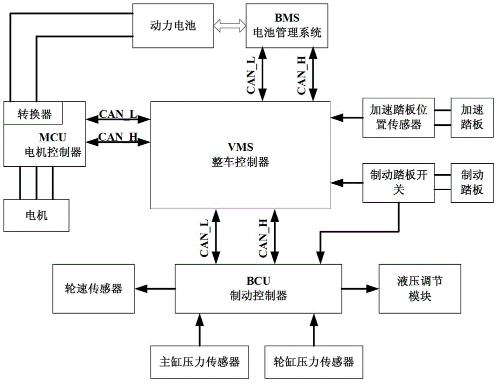
[0026] Example: such as figure 1 As shown in the figure, BMS is the battery management system, MCU is the motor controller, VMS is the vehicle controller, and BCU is the brake controller. The BMS monitors the current state of the power battery in real time, calculates the maximum charging and discharging current allowed to ensure the safety of the vehicle; the MCU controls the operation of the motor, executes the torque requested by the VMS, and feeds back the state of the motor; the VMS is in the BMS, MCU and BCU It acts as a bridge between them, and it communicates with the three controllers through the CAN bus (CAN_H, CAN_L) to realize information exchange. The VMS judges whether the vehicle is currently in a driving state or a braking state by collecting the accelerator pedal position signal and the brake pedal switch signal. When the vehicle is in the driving state, the VMS issues control commands to control the operation of the vehicle. Once the brake pedal is actuated...


PUM


Abstract

The invention discloses a tandem regenerative brake control method. The method comprises the following steps of monitoring the intend of a driver and the state of a vehicle by a vehicle control unit VMS, and judging whether to enter a regenerative brake control mode or not; under a regenerative brake control mode, comprehensively considering the states of a battery and a motor by the vehicle control unit VMS, calculating the currently allowable maximal regenerative brake torque, and transmitting the maximal regenerative brake torque to a brake control unit (BCU); and monitoring the brake requirement of the driver by the brake control unit (BCU), in the range allowed by the vehicle control unit VMS, balancing the regenerative brake torque and the conventional hydraulic brake torque, and on the premise of meeting the brake requirement of the driver, preferentially feeding back the regenerative brake torque to optimally reclaim brake energy. The method can be widely applied to the field of regenerative brake control.

Description

technical field [0001] The invention relates to a regenerative braking control method of an electric vehicle, in particular to a serial regenerative braking control method. Background technique [0002] With the further aggravation of the energy crisis and environmental deterioration, the research and development of energy-saving and environmentally friendly new energy vehicles has received more widespread attention. Compared with traditional fuel vehicles, some or all of new energy vehicles use clean energy as power, which greatly reduces pollution and energy consumption. Electric vehicles are currently the mainstream new energy research and development models. How to improve energy utilization and driving range has become one of the bottlenecks restricting its development. The current solutions mainly include the breakthrough of battery technology and the research and development of braking energy recovery system. The research and development of energy recovery system is...

Claims


Application Information

Patent Timeline
IPC IPC(8): B60T8/171B60L7/18
Inventor 王换换
Owner CHERY AUTOMOBILE CO LTD
Why Eureka
Try Eureka