

Aircraft brake control architecture having improved antiskid redundancy
a technology of anti-skid redundancy and control architecture, which is applied in the direction of aircraft braking arrangement, process and machine control, instruments, etc., can solve the problems of uncontrolled braking due to failure, presenting a unique set of operational and safety problems, and affecting the safety of passengers,
- Summary
- Abstract
- Description
- Claims
- Application Information
AI Technical Summary
Problems solved by technology
Method used
Image

Examples
Embodiment Construction
[0016]The present invention will now be described with reference to the drawing, in which like reference labels are used to refer to like elements throughout.
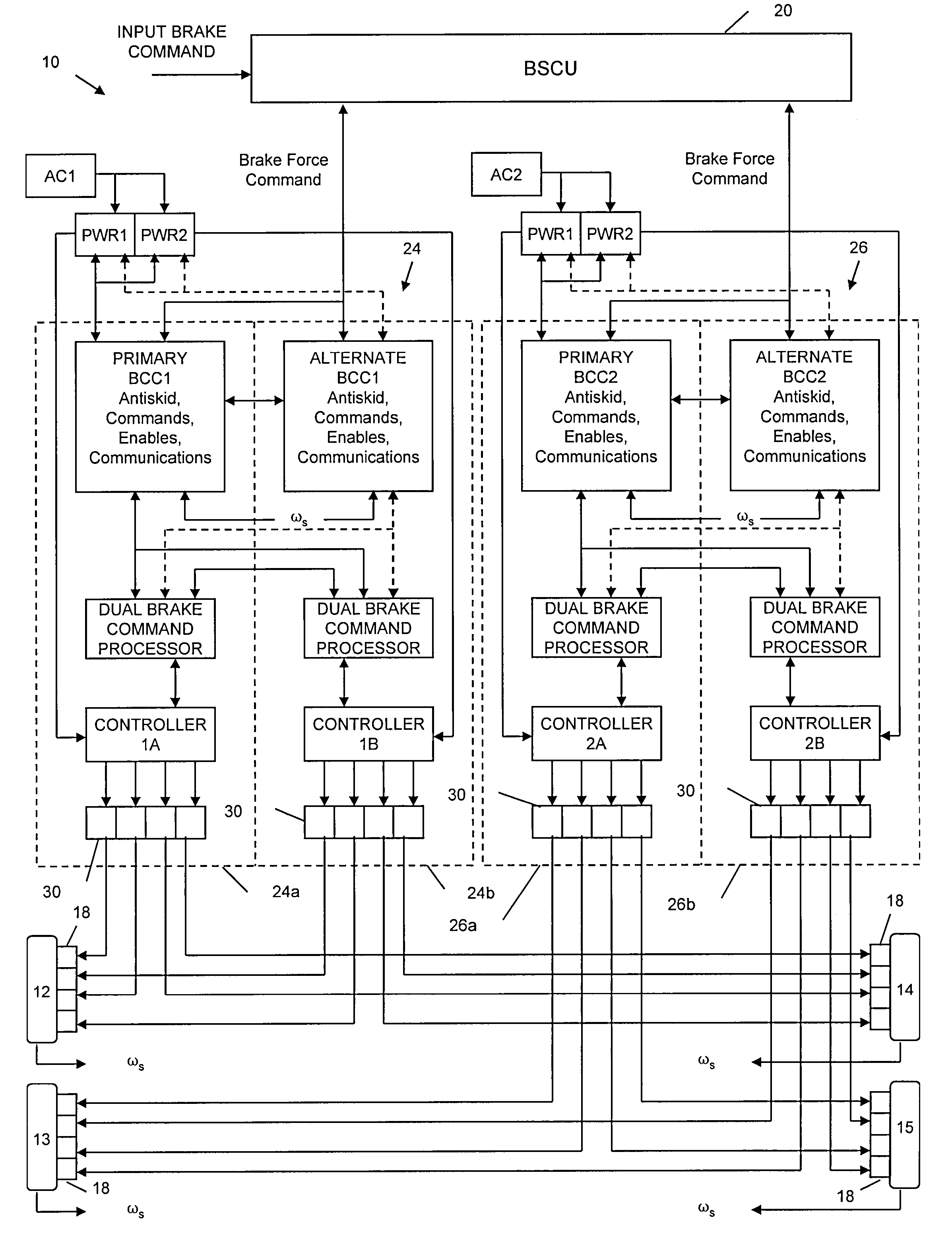
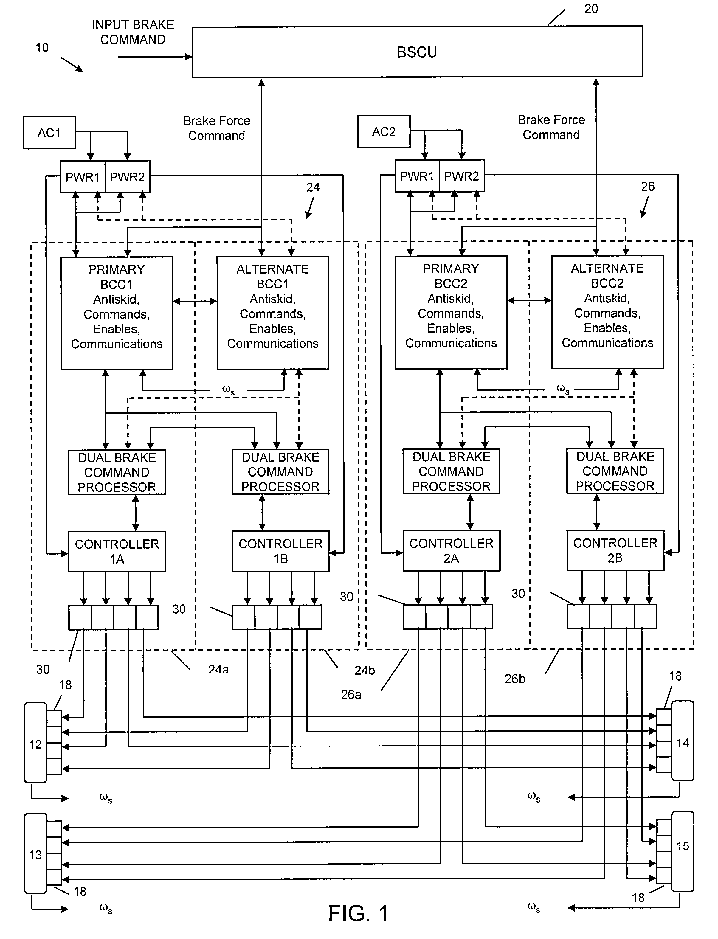
[0017]Referring to FIG. 1, a braking system 10 for an aircraft is shown in accordance with the invention. The braking system 10 is shown as providing braking with respect to four wheels 12-15 each having four independent actuators 18. Wheels 12 and 13 represent a first wheel pair corresponding to a left side of the aircraft. Similarly, wheels 14 and 15 represent a second wheel pair corresponding to the right side of the aircraft. It will be appreciated, however, that the present invention may be utilized with essentially any number of wheels, actuators per wheel, etc.
[0018]The braking system 10 includes an upper level controller 20, or brake system control unit (BSCU), for providing overall control of the system 10. Such BSCU controller may be in accordance with any conventional method such as that described in the aforemention...
PUM
 Abstract
Description
Claims
Application Information