Vehicle braking control system

a control system and vehicle technology, applied in the direction of braking systems, electric devices, battery/cell propulsion, etc., can solve the problems of hydraulic braking devices and electric braking devices consuming electric power, and reducing so as to improve the energy efficiency of the entire vehicle and excellent control response characteristics

Inactive Publication Date: 2005-06-28
NISSAN MOTOR CO LTD
View PDF17 Cites 61 Cited by
  • Summary
  • Abstract
  • Description
  • Claims
  • Application Information

AI Technical Summary

Benefits of technology

[0008]In view of the above, it is conceivable that, in addition to the two above-noted braking devices, providing a regenerative braking device that brakes the wheels by converting the kinetic energy of the vehicle into electric energy, which is known in the art (Japanese Laid-Open Patent Publication No. 2002-106619, and other publications), and storing the subsequently derived electric energy (electric power) in a battery during the operation of the regenerative braking device, can improve the energy efficiency for the entire vehicle.
[0009]An object of the present invention is to provide a vehicle braking system that comprises a regenerative braking device, a hydraulic braking device, and an electric braking device, which are configured to provide excellent control response characteristics in this manner.

Problems solved by technology

It has been discovered that both hydraulic braking devices and electric braking devices consume electric power and that the energy efficiency for the entire vehicle is reduced by the power consumption of using both of these types of braking devices independently.
In particular, hydraulic braking devices consume electric power in the sense that they require electric power for hydraulic pressure control even though the wheels are braked by a brake unit that responds to hydraulic pressure.
These conventional vehicle braking devices are used together in such a manner that they do not allow the energy efficiency for the entire vehicle to be taken into account.
Therefore, not only is the energy efficiency for the entire vehicle poor, but batteries and large generators that can supplement power consumption by using two braking devices must also be placed onboard the vehicle.
Thus, concerns arise in that the configuration is disadvantageous with regard to cost, and the engine fuel consumption for driving the generators worsens.

Method used


Image

  • Vehicle braking control system
  • Vehicle braking control system
  • Vehicle braking control system

Examples


Embodiment Construction

[0022]Selected embodiments of the present invention will now be explained with reference to the drawings. It will be apparent to those skilled in the art from this disclosure that the following descriptions of the embodiments of the present invention are provided for illustration only and not for the purpose of limiting the invention as defined by the appended claims and their equivalents.

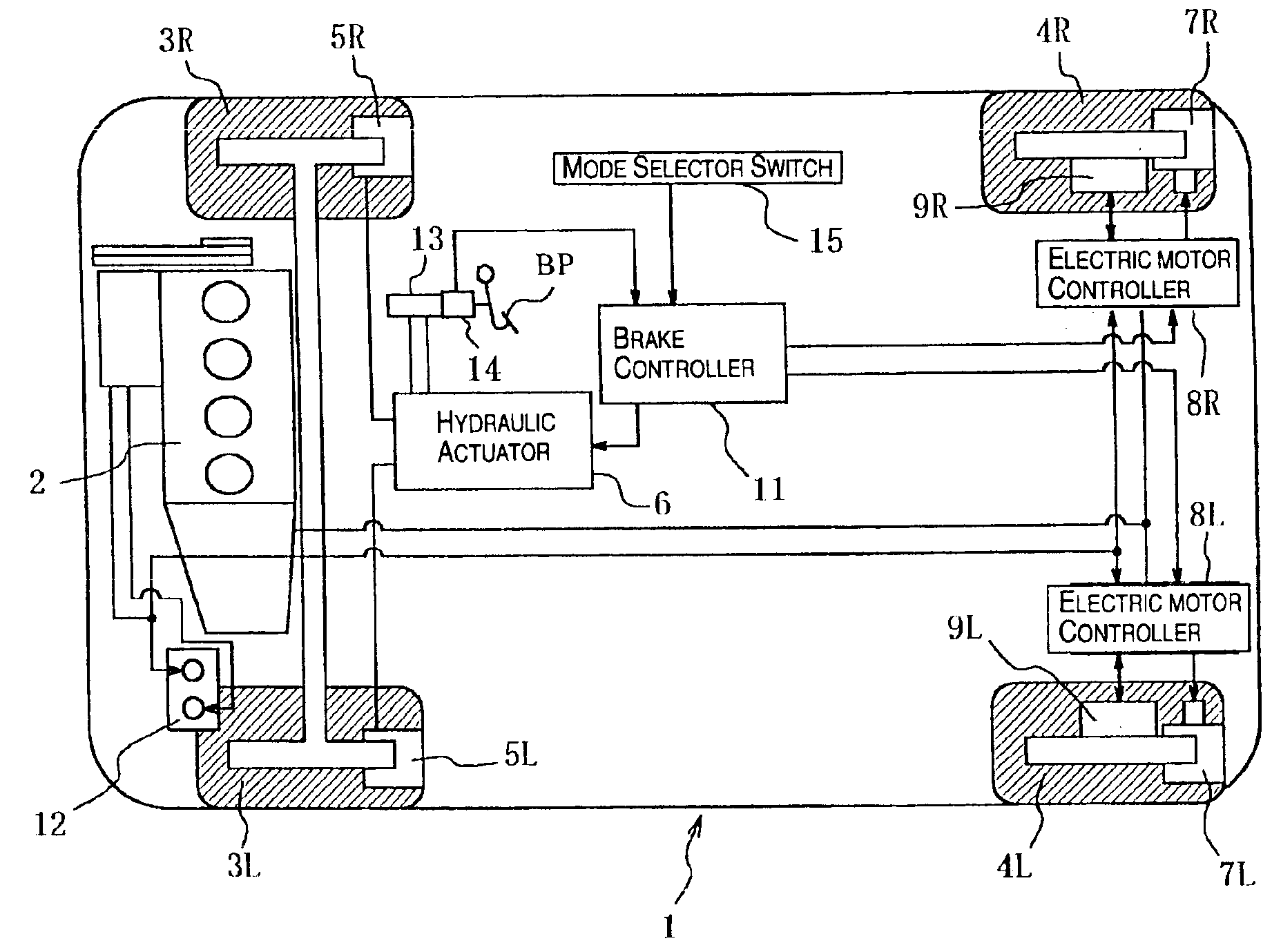
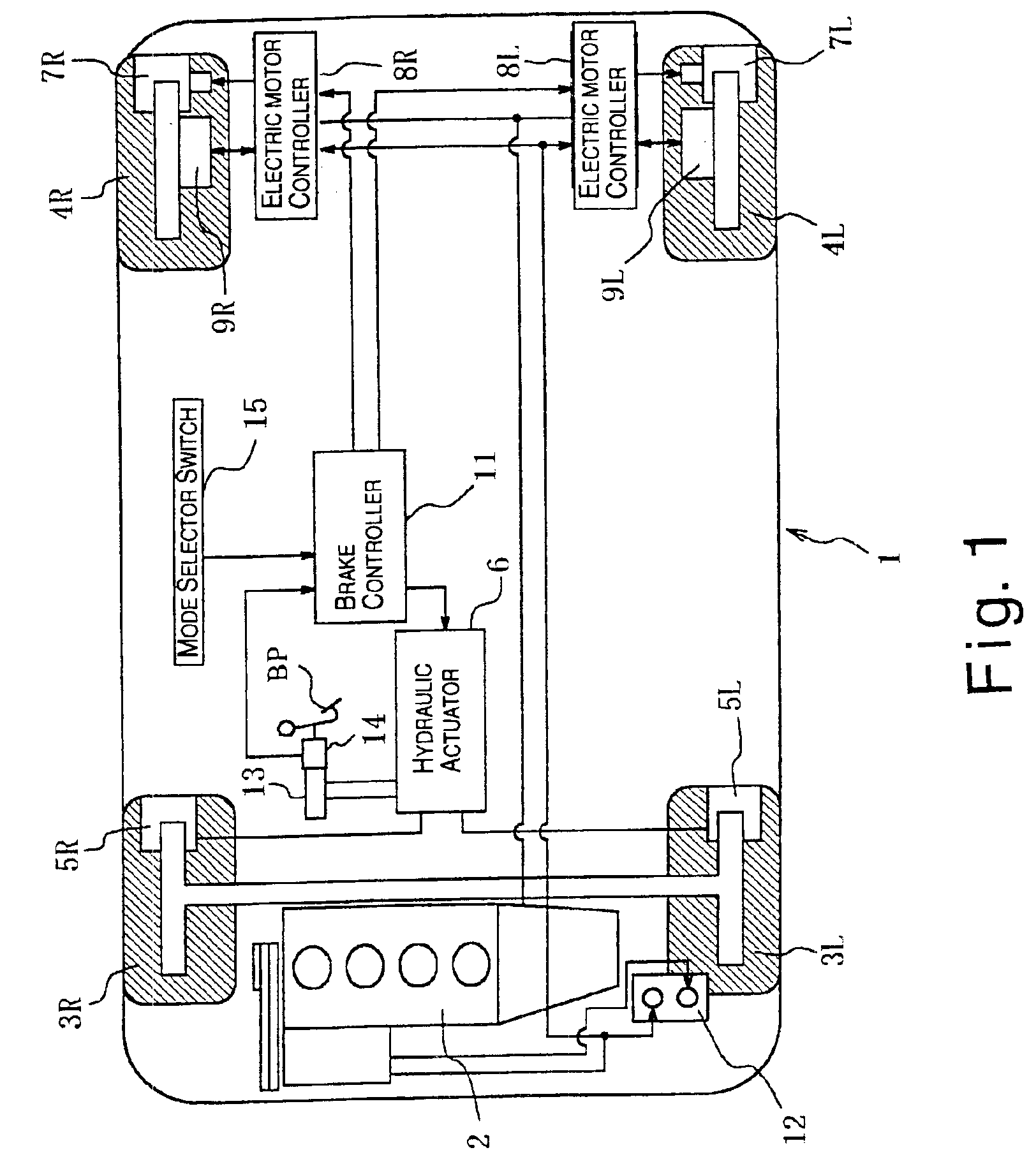
[0023]Referring initially to FIG. 1, a vehicle 1 is diagrammatically illustrated that is equipped with a vehicle braking control system in accordance with a first embodiment of the present invention. The vehicle 1 includes an engine 2, a pair of (left and right) front wheels 3L and 3R and a pair of (left and right) rear wheels 4L and 4R. While the vehicle 1 is illustrated as a front wheel drive vehicle, the present invention can be used with rear wheel drive and four wheel drive vehicles.

[0024]The vehicle braking system of the present embodiment is configured and arranged such that the left and rig...


PUM


Abstract

A vehicle braking control system is provided that controls at least three braking devices including a regenerative braking device, a hydraulic braking device and an electric braking device. The vehicle braking control system basically comprises a braking mode selecting section, a required braking force determining section and a target braking force setting section. The braking mode selecting section sets one of a plurality of braking modes having a different braking control priority for each of the target braking forces. The required braking force determining section determines a required braking force for an entire vehicle. The target braking force setting section sets each of the target braking forces based on the braking control priority of the selected braking mode to produce the required braking force for the entire vehicle. Preferably, the braking mode selecting section set at least an electric power maintenance priority mode and a braking response priority mode.

Description

BACKGROUND OF THE INVENTION[0001]1. Field of the Invention[0002]The present invention generally relates to a vehicle braking control system that controls a plurality of braking devices or systems. More specifically, the present invention relates to a vehicle braking control system with excellent control response characteristics, and that comprises at least three braking devices including a regenerative braking device, a hydraulic braking device and an electric braking device.[0003]2. Background Information[0004]Previously, a vehicle has been proposed that is equipped with both a hydraulic braking system and an electric braking system for applying a braking force for the entire vehicle. One example of such a vehicle equipped with both hydraulic and electric braking systems is described in Japanese Laid-Open Patent Publication No. 2000-255401. The vehicle disclosed in this publication has the hydraulic braking system configured to serve as a front wheel braking system and the electric...

Claims


Application Information

Patent Timeline
Patent Type & Authority Patents(United States)
IPC IPC(8): B60T1/10B60T13/74B60T10/00B60T1/00B60T13/00B60T8/26B60T8/00B60T8/17B60L7/22B60L7/24B60L7/26
CPCB60L7/22B60L7/26B60T1/10B60T8/00B60T8/267B60T13/741B60L11/123B60T10/00Y02T10/6217B60T2270/608B60L2220/44Y02T10/7077B60L50/61Y02T10/62Y02T10/70Y02T10/7072
Inventor TSUNEHARA, HIROSHI
Owner NISSAN MOTOR CO LTD
Why Eureka
Try Eureka