Dynamic brake for power door

a technology for power doors and brakes, applied in the direction of dynamo-electric converter control, dc motor speed/torque control, dc motor rotation control, etc., can solve the problems of large doors in such door systems, difficult environment for door systems to operate in, and general requirement for very rapid operation

Inactive Publication Date: 2001-01-16
WESTINGHOUSE AIR BRAKE CO
View PDF12 Cites 60 Cited by
  • Summary
  • Abstract
  • Description
  • Claims
  • Application Information

AI Technical Summary

Benefits of technology

It is therefore one of the primary objects of the present invention to provide an apparatus for stopping a power door which operates in an open loop mode and does not require a functioning position encoder.
Another object of the present invention is to provide an apparatus for stopping a power door which operates in an open loop mode and does not require a functioning logic device to process position or speed of the door.
Yet another object of the present invention is to provide an apparatus for stopping a power door which does not generate significant heat in a control cabinet for the door.
A further object of the present invention is to provide an apparatus for stopping a power door which does not tend to overshoot as the door is stopped.
It is an additional object of the present invention to provide an apparatus for stopping a power door which can function in either the door closing or the door opening direction.
A further object of the present invention is to provide an apparatus for stopping a power door which prevents motion of the door after it has been stopped.

Problems solved by technology

Such door systems must operate in a rather challenging environment in which the safety of the public may be at stake.
Additionally, these door systems are subjected to heavy usage and are generally required to operate very rapidly.
Furthermore, the doors in such door systems are often quite massive and must be stopped very rapidly in the event that an obstruction is detected to avoid crushing a person in the path of a door.
One difficulty with this approach is that the kinetic energy of the door(s) is regeneratively converted to electrical energy which is fed back to the power distribution line which provides power to the doors.
Since it is necessary to stop the doors very quickly in the event of an obstruction, this regenerative energy is fed to the power distribution line during a very short time interval and causes a spike of voltage in the power distribution line.
This may cause the entire door system to fail.
Another difficulty is that oscillations may occur, the velocity of the door(s) overshooting zero speed and changing polarity.
Another difficulty with this approach is that it is not fail safe.
If the logical device malfunctions when the door(s) are in motion, the doors will continue to move and may injure a person in their path.
This approach has two principal difficulties.
The maximum allowed deceleration of the door is limited by the strength of the door drive hardware which connects the motor to the door(s), and may also be limited by electrical considerations.
Such doors are more likely to cause harm to a person than doors which are stopped with a motor current which remains constant through most of the stopping event, because the latter doors stop in a shorter distance.
Another disadvantage of the shunt resistor approach is that if the shunt is located in the door control enclosure, its heat is generated in the enclosure and may cause overheating of the electronic components.
A further disadvantage of the shunt resistor approach is that as the motor ages, its magnetic field becomes weaker.

Method used


Image

  • Dynamic brake for power door
  • Dynamic brake for power door
  • Dynamic brake for power door

Examples


Embodiment Construction

, particularly, when the detailed description is taken in conjunction with the attached drawing figures and with the appended claims.

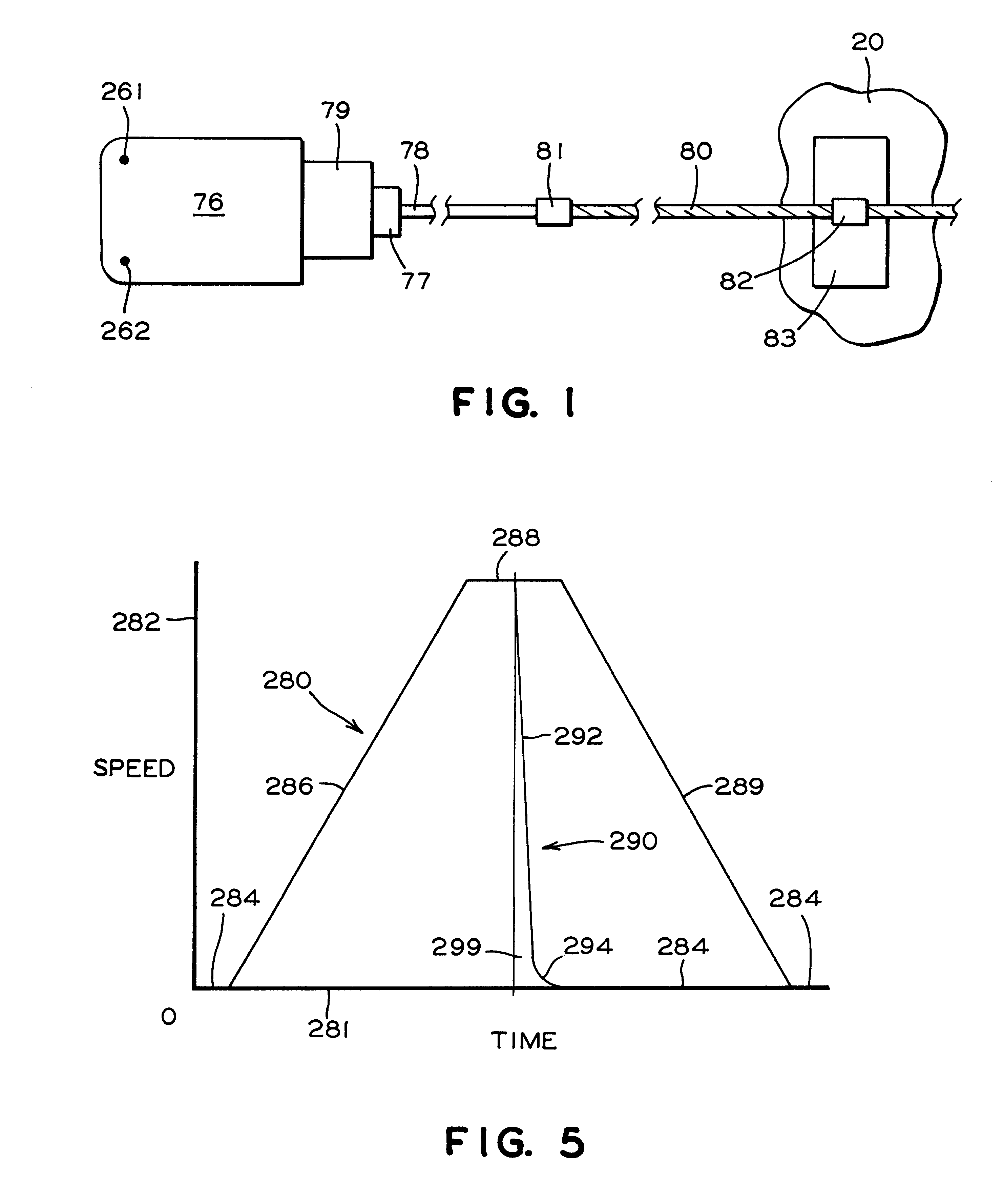
FIG. 1 is a mechanical schematic of a power door to which a presently preferred embodiment of the invention is applied;

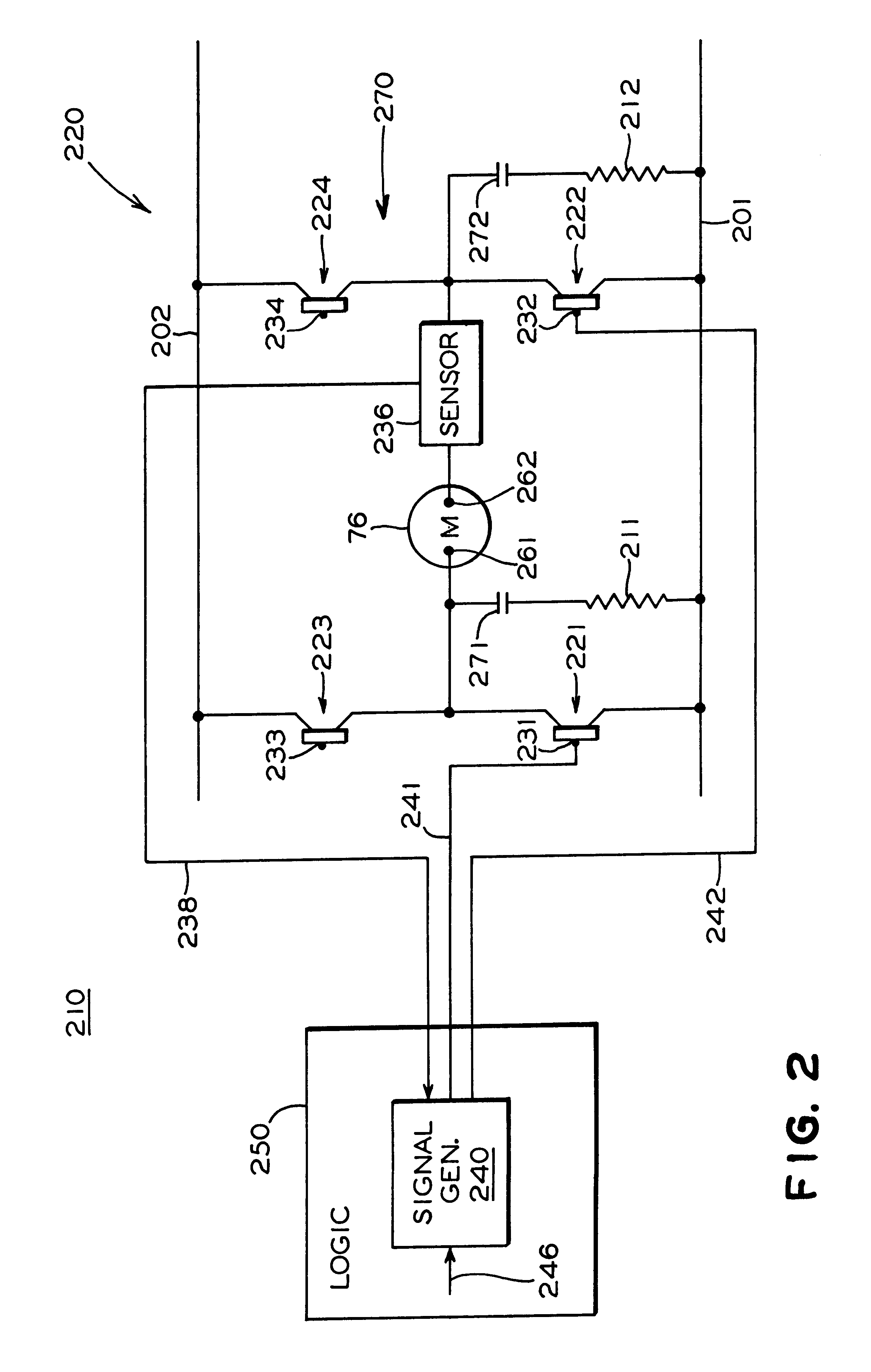
FIG. 2 is an electrical schematic of a presently preferred embodiment of the dynamic brake of the invention in which a current feedback signal is obtained from a current sensor in series with the motor;

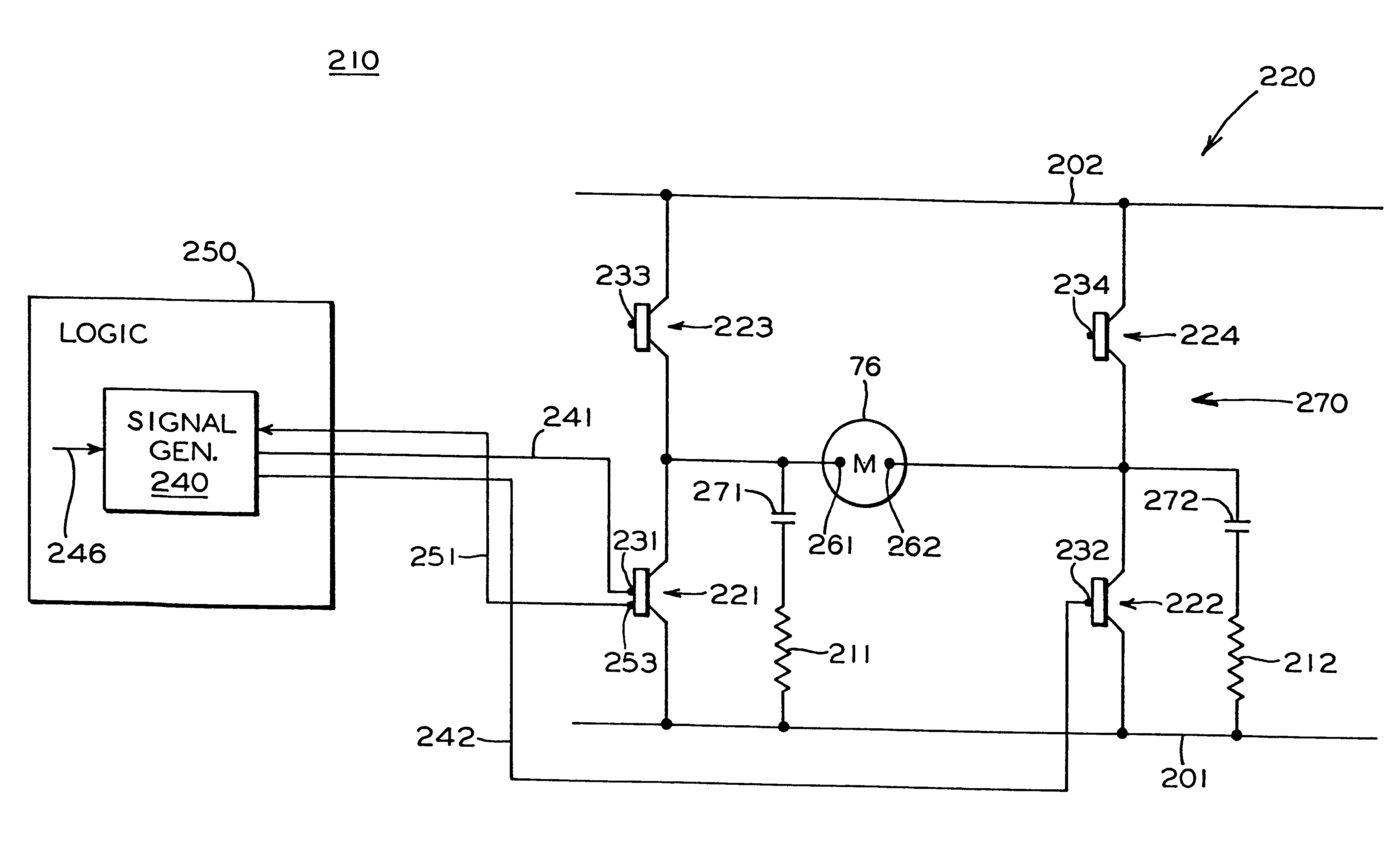
FIG. 3 is an electrical schematic of a presently preferred embodiment of the invention in which a current indicating signal is obtained from a current indicating terminal on a first transistor;

FIG. 4 is an electrical schematic of a presently preferred embodiment of the invention in which a current indicating signal is obtained from a current indicating terminal on a second transistor;

FIG. 5 is a plot of velocity versus time for a power door for a normal closing cycle and for an emergency stop with the dynamic brake of the invention; and

F...


PUM


Abstract

The invention is a dynamic brake for a power door which is moved by an electric motor having at least two terminals. The motor is energized by a pulse width modulated door drive amplifier connected to a first power line and a second power line. The door drive amplifier has a first group of switches connecting the motor terminals to the first power line and it has a second group of switches connecting the motor terminals to the second power line. The dynamic brake has a brake control signal generator connected to receive an input signal indicative of a need to apply the dynamic brake and it has at least one output signal line connected to a control input of at least two of the switches in the first group of switches. The brake control signal generator responds to the input signal indicative of a need to apply the dynamic brake by supplying at least one control signal to the control inputs of at least two switches in the first group of switches so that the control signal(s) cause at least two switches to conduct and provide at least one dynamic brake current circuit for a braking current driven by an emf of the motor and hence dynamically braking the motor.

Description

The present invention relates, in general, to braking systems for power door systems and, more particularly, the instant invention relates to braking systems for transit vehicle door systems and / or elevator doors.Power door systems for use on elevators, transit vehicles, etc., which are generally intended for the general public, have been well known in the art prior to the development of the present invention. Such door systems must operate in a rather challenging environment in which the safety of the public may be at stake. Additionally, these door systems are subjected to heavy usage and are generally required to operate very rapidly. Furthermore, the doors in such door systems are often quite massive and must be stopped very rapidly in the event that an obstruction is detected to avoid crushing a person in the path of a door.An electric motor for such a power door system may be powered by a pulse width modulated H-bridge amplifier. Typically, the motor is a DC motor in which the...

Claims


Application Information

Patent Timeline
Patent Type & Authority Patents(United States)
IPC IPC(8): H02P7/00
CPCH02P7/0044H02P7/04
Inventor CALAMATAS, PHILIP J.
Owner WESTINGHOUSE AIR BRAKE CO
Why Eureka
Try Eureka