Pneumatic tool with side exhaust

a pneumatic tool and side exhaust technology, applied in the field of pneumatic tools, can solve problems such as safety hazards during the operation of pneumatic tools

Inactive Publication Date: 2000-04-04
BRUNNHOELZL RACING
View PDF15 Cites 54 Cited by
  • Summary
  • Abstract
  • Description
  • Claims
  • Application Information

AI Technical Summary

Problems solved by technology

One problem associated with forward exhaust pneumatic tools is that dust particles and other debris positioned on a work surface are driven by the exhaust gas into the face of the user, causing a safety hazard during operation of the pneumatic tool.

Method used


Image

  • Pneumatic tool with side exhaust
  • Pneumatic tool with side exhaust
  • Pneumatic tool with side exhaust

Examples


case 71

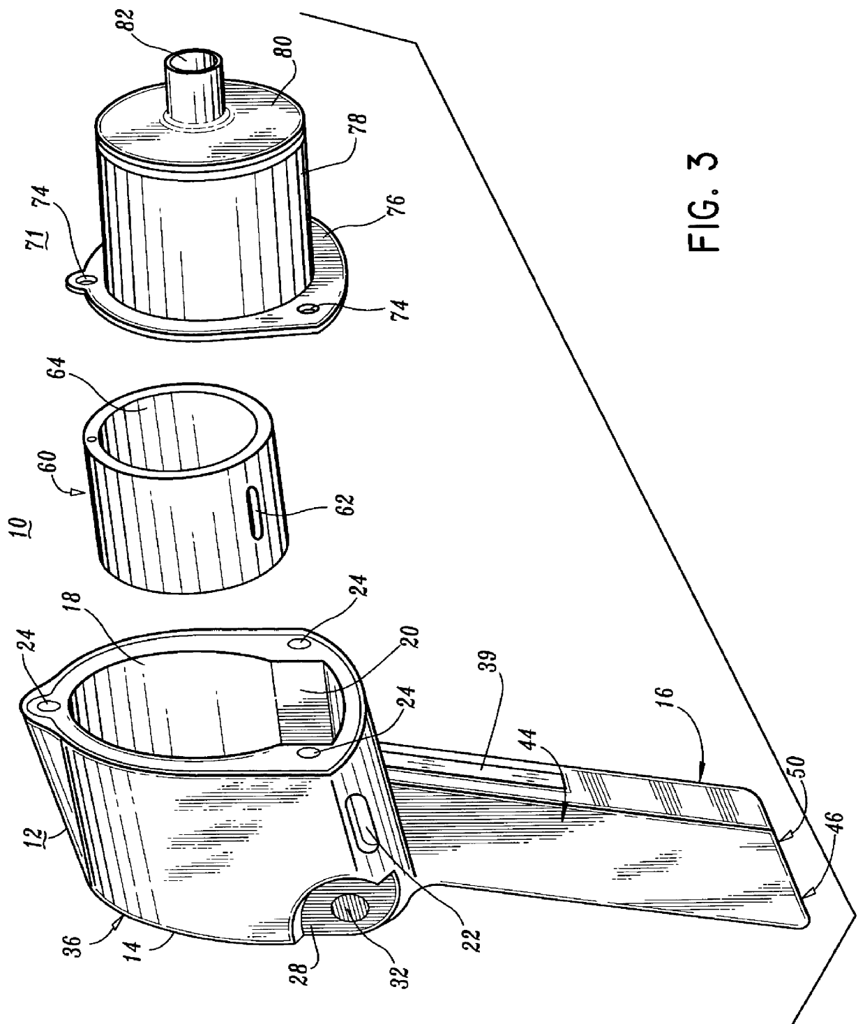
A first hammer case 71 is pneumatically sealed and removably fastened over the first motor housing cylinder receptacle 18 utilizing a plurality of hammer case cap screws 72 through a plurality of first hammer case rear plate cap screw openings 74. The first hammer case 71 consists of a first hammer case rear plate 76 which lacks an exhaust port described in the prior art. The first hammer case rear plate 76 is pneumatically sealed and securely fastened to a first hammer case middle cylinder 78. The first hammer case middle cylinder 78 is pneumatically sealed and securely fastened to a first hammer case front plate 80 having a first hammer case anvil receptacle 82 therein. Within the first hammer case 71 is a hammer 70 which comprises a hammer frame 86 having a pair of hammer frame pins 88 inserted through respective hammer frame pin receptacles 90. Within the first hammer case 71 is a pair of hammers 70 through which an anvil 180 is positioned. A hammer case gasket is positioned adj...


PUM

PropertyMeasurementUnit
rotationaaaaaaaaaa
noise levelaaaaaaaaaa
pressureaaaaaaaaaa

Abstract

The present invention relates to a pneumatic tool having a housing including a motor housing portion which is pneumatically and securely connected to a handle housing portion. The motor housing portion has a motor housing exhaust opening with a motor housing exhaust opening port therethrough. The motor housing exhaust opening port functions to direct pressurized air from a forward direction to a sideways direction.

Description

1. Technical FieldThe present invention relates to a pneumatic tool. More particularly, the present invention relates to a pneumatic tool having a handle housing portion and a motor housing portion and a side exhaust formed in a sidewall of the motor housing portion.2. Background of Related ArtPneumatic tools, such as impact wrenches, are well known in the prior art. Prior art pneumatic tools include an air driven rotor having an air inlet port and an air exhaust port. Typically, the air exhaust port is positioned to direct air exhaust from the front of the tool in a forward direction. One problem associated with forward exhaust pneumatic tools is that dust particles and other debris positioned on a work surface are driven by the exhaust gas into the face of the user, causing a safety hazard during operation of the pneumatic tool.Numerous innovations for pneumatic impact tools have been provided in the prior art. Even though these innovations may be suitable for the specific individ...

Claims


Application Information

Patent Timeline
Patent Type & Authority Patents(United States)
IPC IPC(8): B25B21/00
CPCB25B21/00
Inventor BRUNHOELZL, GEORGE
Owner BRUNNHOELZL RACING
Why Eureka
Try Eureka