Security device for the lock on a switchgear-cabinet door, machine housing, etc.

a technology for security devices and switch cabinet doors, which is applied in the direction of limiting/preventing/returning parts movement, wing knobs, alarms, etc., can solve problems such as complicated arrangement, and achieve the effects of reducing the risk of theft, facilitating procurement, and increasing the security factor

Inactive Publication Date: 2000-04-25
RAMSAUER DIETER
View PDF16 Cites 22 Cited by
  • Summary
  • Abstract
  • Description
  • Claims
  • Application Information

AI Technical Summary

Benefits of technology

The patent text describes a security mechanism for doors that prevents unauthorized access. The mechanism includes a swivel lever with a special key profile that fits into a corresponding profile in another part fastened to the door frame. When the special key profile penetrates into the other part, a switch is flipped, triggering the same functions as a magnet switch. The advantage of this embodiment form is that it impedes tampering by unauthorized persons. The key profile can be designed to deactivate the security function when the door is open, either for maintenance purposes or by using special tools. The security function can also be deactivated by specially authorized persons with corresponding tools. The key profile is shaped in such a way that it is surrounded by locking mechanisms or tumblers of the other part, making it more difficult for unauthorized persons to tamper with the security function. The one part can be a flat metal piece with notches and/or holes, and the other part, a security switch, has a receiving slot for the flat metal piece, where pins or protuberances can secure the flat metal piece in position. This mechanism prevents unauthorized access to the door and ensures safety.

Problems solved by technology

The technical problem addressed in this patent is to provide a security lock that can be used in a bar lock with swivel lever actuation and additional security features. The lock is designed to secure the door closed and prevent unauthorized individuals from tampering with the lock. The lock is mechanically secure and can be easily installed and unlocked with a key. The invention allows for the use of a single lock that can be used in various embodiment forms of the invention. The lock is designed to be easily installed and unlock the swivel lever, which simplifies the construction and operation of the lock. The lock can be unlocked with a simple mechanical switch or by using a key profile or tumblues. The invention provides a security lock that is mechanically secure and can be easily installed and unlocked with a key.

Method used


Image

  • Security device for the lock on a switchgear-cabinet door, machine housing, etc.
  • Security device for the lock on a switchgear-cabinet door, machine housing, etc.
  • Security device for the lock on a switchgear-cabinet door, machine housing, etc.

Examples


Embodiment Construction

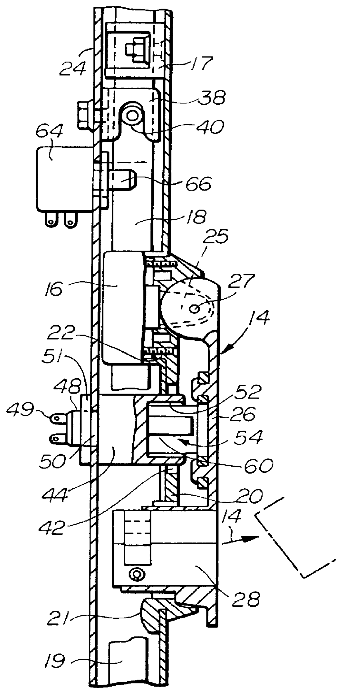
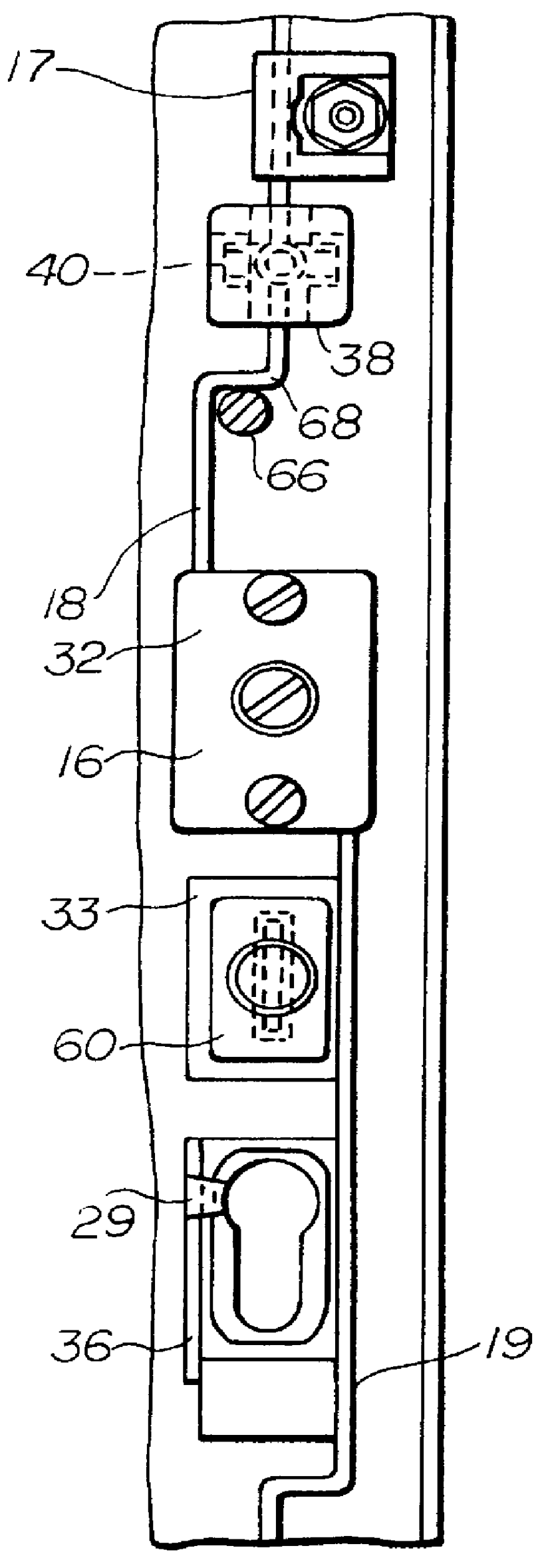
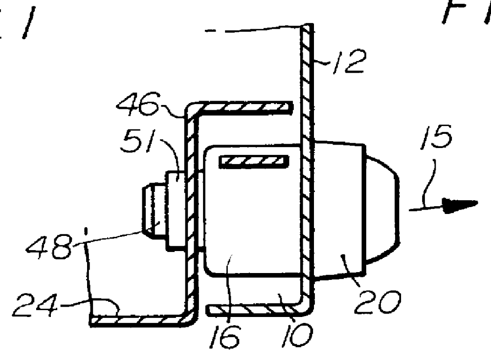
FIG. 1 is a longitudinal sectional view showing a swivel lever bar lock 14 which is arranged in the folded space or bevel space 10 (see FIG. 2 for a cross-sectional view) formed between the beveled door leaf 12 and the beveled opening area of a sheet-metal cabinet body 24. In the arrangement shown in the Figure, the swivel lever bar lock comprises a lock 16 from which bars 18, 19 project so as to extend in the bevel space 10 and are supported inside the lock 16 on one side and, on the other side, also in a displaceable manner at bar guides 17 fastened to the door leaf 12.

The door leaf 12 is articulated at the cabinet body 24 in such a way that it can be swiveled away from the frame region 24 (FIG. 2) in the direction of the arrow 15 shown in FIG. 2.

A base plate or receptacle cavity 20 projects through door leaf holes 36 and 32 by shoulders 21 and 22 projecting from this base plate or receptacle cavity 20, wherein the plate or receptacle cavity 20 is secured in the door leaf by means...


PUM


Abstract

PCT No. PCT/EP96/01079 Sec. 371 Date Nov. 7, 1997 Sec. 102(e) Date Nov. 7, 1997 PCT Filed Mar. 14, 1996 PCT Pub. No. WO96/35851 PCT Pub. Date Nov. 14, 1996Described is a security device for the lock on a switchgear-cabinet door, a machine housing or similar equipment, the device consisting of a first element (54) attached e.g. to the door (12) and a second element (44) attached e.g. to the door frame or machine-housing frame (24), the two elements (54, 44) being designed so that one can be inserted in the other and be held in this position under the control of an electrical signal, corresponding, for example, to the presence or absence of an operating signal. The invention calls, in the case of a door or machine-housing panel (12), for e.g. one element (54) to be attached to the handle (26) of a turning-handle lock (14) mounted on the door or housing panel and for the other element (44) to be attached in such a way to the door frame or housing frame (24) that this other element (44) projects out into the vicinity of the lock handle when the door is closed or the housing in place and the lock handle turned into the "locked" position.

Description


Claims


Application Information

Patent Timeline
Owner RAMSAUER DIETER
Why Eureka
Try Eureka