Connector for printed circuit boards

Inactive Publication Date: 2000-05-02
JST MFG CO LTD +1
View PDF2 Cites 80 Cited by
  • Summary
  • Abstract
  • Description
  • Claims
  • Application Information

AI Technical Summary

Problems solved by technology

Due to their repeated swing to the pressing position, those recesses 52 formed of the plastics are likely to undergo deformation such that the cover's force of pressing the flexible printed

Method used


Image

  • Connector for printed circuit boards
  • Connector for printed circuit boards
  • Connector for printed circuit boards

Examples


Embodiment Construction

Some preferable embodiments of the present invention will now be described in detail referring to the drawings.

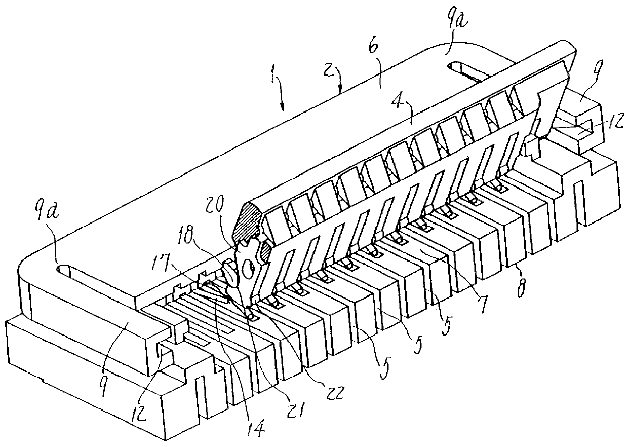
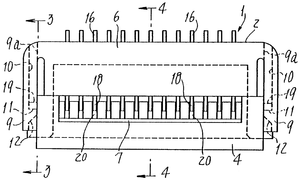
In an embodiment of the present invention, a connector as shown in FIGS. 1 and 2 is provided for use with printed circuit boards. Similarly to the prior art connectors as summarized above and known in the art, the connector 1 comprises an insulating housing 2, a plurality of base contacts 3 (see FIG. 4) secured in the housing at regular intervals, and an insulated pressing cover 4 swingably attached to the hosing 2.

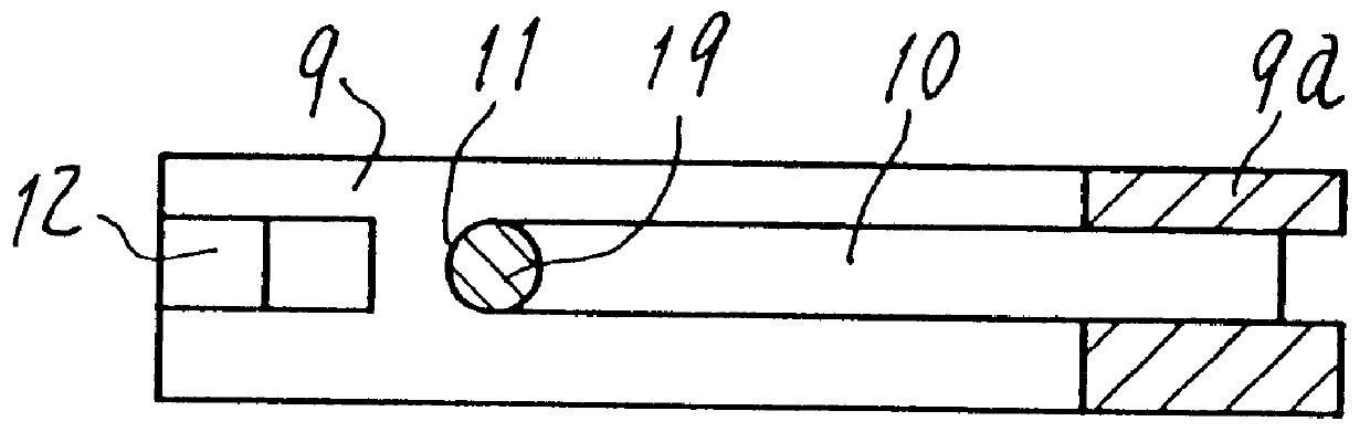
The housing 2 made of an appropriate insulating material such as LCP is of a flat rectangular parallel-piped shape extended in a longitudinal direction (`sideways` in the drawings). Contact receiving grooves 5 formed in the housing at regular intervals extend fore to aft and perpendicular to the longitudinal direction. A top horizontal wall 6 of the housing has an imaginary frontal region cut off to provide an open recess 7 opened upward. A pair of arm-shaped hol...


PUM


Abstract

A connector for printed circuit boards, particularly for flexible ones such as FPC or FFC, has an insulating housing (2) with a recess (7) opened up and base contacts (3) held in the housing at regular intervals and each having a resilient beam (14) and an arm (5) integral with the beam. Each beam has a conductive protrusion (17) in the recess, and each arm extending along the housing's top into the recess has a pivotal end (18) facing the protrusion. An insulated pressing cover (4) engaging with the pivotal ends is rotatable between its pressing position adjacent to and its releasing position remote from the protrusions. The pivotal ends (18) lock the cover then pushing the circuit board (30) against the resilient beams (14). The cover has cover contacts (20) rotatably engaging with the pivotal ends and corresponding to the base contacts (3), so that the pivotal ends, the cover contacts (20) and the printed circuit board (30) are electrically connected to each other at the pressing position.

Description

1. Field of the InventionThe present invention relates to a connector adapted for attachment to flexible printed circuit boards such as the so-called flexible printed cables ("FPC") or flexible flat cables ("FFC") that have to be electrically connected to electric or electronic devices or apparatuses.2. Prior ArtAn example of those connectors known in the art and designed for use with flexible printed circuit boards is disclosed in the Japanese Laying-Open Gazette of Unexamined Utility Model No. 6-77186. As shown in FIGS. 12 and 13 accompanying the present specification, such a prior art connector comprises an insulating housing 41 having a horizontal top wall 42 whose front portion is cut off to provide an accessible opening or space 43 opened forward and upward. A plurality of conductive contacts 45 are installed in the housing 41 at regular intervals and in a direction perpendicular to the drawing figures. Each contact 45 has a resilient beam 47 U-shaped in cross section and exte...

Claims


Application Information

Patent Timeline
IPC IPC(8): H01R12/24H01R12/00H01R12/79H01R12/88
CPCH01R12/79H01R12/88
Inventor MATSUMOTO, HARUHIKOEBINE, NOBUHITOSEKIGUCHI, TOSHIKAZU
Owner JST MFG CO LTD
Why Eureka
Try Eureka