Mutual inductor handover test device and test method thereof

A technology of handover test and test method, applied in the field of transformer handover test device, can solve problems such as poor contact, limited nut area, leakage short-circuit, etc., to ensure firm clamping, shorten test time, and improve contact reliability.

Active Publication Date: 2020-07-10
GUIZHOU POWER GRID CO LTD
View PDF6 Cites 3 Cited by
  • Summary
  • Abstract
  • Description
  • Claims
  • Application Information

AI Technical Summary

Problems solved by technology

[0014] The second aspect: when performing test wiring and short-circuiting on the secondary terminals of the transformer, it is also a time-consuming and laborious problem to reliably connect the test line and short-circuit the secondary terminals of the transformer
Due to the certain elasticity of bare wires, coupled with the limited area of ​​each secondary terminal nut, and the smooth surface of the nut, multiple strands of bare wires are easy to slip off from the nut
When using the nut tightening method, it is necessary to loosen all the nuts, then wind them with bare wires, and then tighten the nuts. Because the wires are soft, it is easy to cause poor contact due to loose crimping, and it is time-consuming and laborious.
[0016] (2) The traditional test wire clamp is also used to short-circuit the secondary terminal in the test, but due to the limited area of ​​the terminal nut and the smooth surface of

Method used


Image

  • Mutual inductor handover test device and test method thereof
  • Mutual inductor handover test device and test method thereof
  • Mutual inductor handover test device and test method thereof

Examples


Embodiment 1

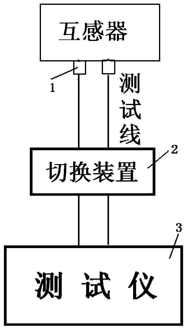
[0058] Embodiment 1: as Figure 1-12 Shown, a transformer handover test device, including a test line clamp 1, a switching device 2 and a tester 3, the test line clamp 1 is connected to the input end of the switching device 2 through a test line, and the test port of the switching device 2 is connected to the tester 3. The test clamp 1 can pinch the screw on the secondary side terminal of the transformer, the switching device 2 connects and short-circuits the secondary winding of the transformer, and the tester 3 includes an insulation resistance tester, a transformation ratio tester, and a transformer characteristic tester and DC resistance tester.

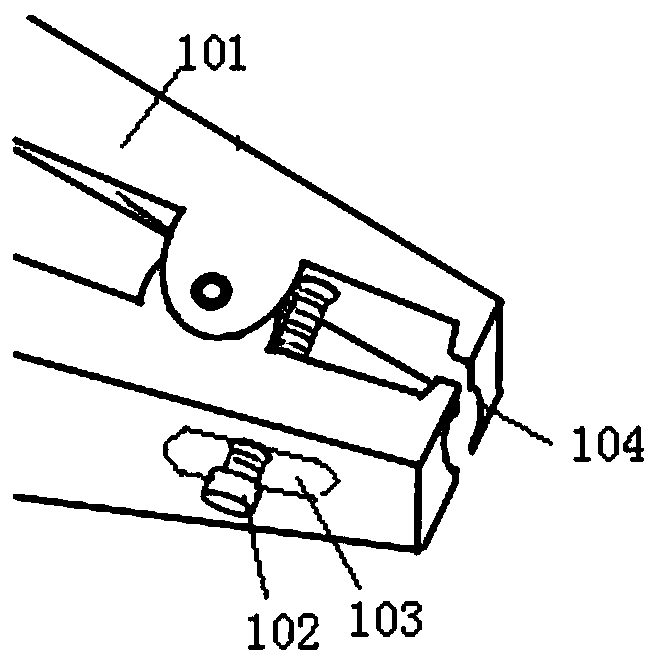
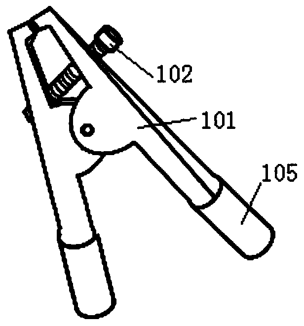
[0059] Preferably, the above-mentioned test wire clamp 1 adopts an alligator clip structure, including two clamps 101 that are mutually rotatably connected and a return spring located at the rotational connection of the two clamps 101, and two symmetrical arc-shaped occlusal jaws are arranged at the front ends of the two clamps 1...

Embodiment 2

[0070] Embodiment 2: A test method of a transformer handover test device, the method is: according to the test sequence of the test items of the transformer, an insulation test is first performed, and then a characteristic test is performed. The following is the switching instructions when using the switching device for testing according to this test sequence: Before testing, connect the test lines L1~L8 with the first, second, third, and fourth secondary windings of the switching device in the switching circuit. Connect the test line output sockets I+, U+; U-, U+ respectively, and then connect the other ends of the test lines L1~L8 to 1S1, 1S2 of the secondary winding of the transformer respectively; 2S1, 2S2 of 2S; 3S1, 3S of 3S. 3S2; connect 4S1 and 4S2 of 4S, ground the E end of the test port, conduct a secondary insulation resistance test, an insulation resistance test for grounding between secondary windings, a transformation ratio test, an excitation characteristic and p...


PUM


Abstract

The invention discloses a mutual inductor handover test device and a test method thereof. The device comprises a test wire clamp, a switching device and a tester. The test wire clamp is connected to the input end of the switching device through a test wire. A test port of the switching device is connected to the tester, the test wire clamp can clamp a screw of a secondary side terminal of the mutual inductor, the switching device is used for connecting and short-circuiting a secondary winding of the mutual inductor, and the tester comprises an insulation resistance tester, a transformation ratio tester, a mutual inductor characteristic tester and a direct-current resistance tester. According to the invention, through using the test wire clamp, the switching device and different testers, the test wire clamp is connected with the switching device, the switching device is connected to the secondary winding of the mutual inductor at a time, various tests are achieved when the mutual inductor is handed over, the functions of open circuit, short circuit and grounding operation of the secondary side winding are rapidly completed only through switching of the switching device, the test time is shortened, and the test efficiency is improved.

Description

technical field [0001] The invention relates to a transformer handover test device and a test method thereof, and belongs to the technical field of transformer handover test equipment. Background technique [0002] At present, when we are testing the transformer, the test items are as follows: [0003] insulation test Characteristic test 1. Primary to secondary insulation resistance 4. Ratio 2. Primary to secondary AC withstand voltage 5. Excitation characteristics, polarity calibration, secondary winding direct resistance 3. Insulation resistance to ground between secondary windings [0004] During the test, there were two problems: [0005] First aspect: For the above test items, the position of the test line that needs to be connected to the secondary terminal is different, and the state of the short circuit of the outgoing terminal of the secondary winding is also different. It is necessary for the tester to frequently change the test...

Claims


Application Information

Patent Timeline
IPC IPC(8): G01R31/72G01R27/02G01R31/14G01R1/04G01R1/20
CPCG01R27/025G01R27/02G01R31/14G01R1/0416G01R1/20
Inventor 史纯清岑荣佳罗家猛黄俊澄易洵刘超田小林肖玉斌张健华赵鹏程罗芳刘昌宏石廷章犹永开杨大明柏文健赖罗彬吴昊杨凌典文雯禹海林余钢王江会冯明宇张莹
Owner GUIZHOU POWER GRID CO LTD
Why Eureka
Try Eureka