Jig frame for drop test of flat panel display device

a flat panel display and drop test technology, applied in measurement devices, scientific instruments, instruments, etc., can solve the problems of user inadvertent drop troublesome testers, and inability to adjust the weight and degree of deformation of mobile electronic devices, so as to reduce the drop test time and effectively identify the

Inactive Publication Date: 2011-06-28
SAMSUNG DISPLAY CO LTD
View PDF19 Cites 48 Cited by
  • Summary
  • Abstract
  • Description
  • Claims
  • Application Information

AI Technical Summary

Benefits of technology

[0014]Exemplary embodiments of the present invention provide a jig frame for a drop test of a flat panel display, which is designed to allow a tester to effectively identify if the flat panel display is damaged and reduce the drop test time.
[0015]Exemplary embodiments of the present invention also provide a jig frame for a drop test of a flat panel display, which is designed to easily adjust its weight and degree of deformation and thus to effectively meet a variety of different conditions of an electronic device to which the flat panel display will be applied.

Problems solved by technology

Particularly, when the flat panel display is applied to a mobile electronic device, the user may inadvertently drop the mobile electronic device.
This is troublesome for the tester.
Additionally, the typical jig frame is provided in the form of a fixed structure, it is impossible to adjust its weight and degree of deformation.
Therefore, the typical jig frame cannot meet a variety of conditions of the electronic device to which the flat panel display will be applied.
Further, since the typical jig frame is not durable, bolt coupling portions of the jig frame may be easily damaged.
Furthermore, since 10 or more bolts must be coupled and released for each drop test, the drop test is time-consuming.
This causes dispersion of the jig frame and thus deteriorates the reliability of the drop test.

Method used


Image

  • Jig frame for drop test of flat panel display device
  • Jig frame for drop test of flat panel display device
  • Jig frame for drop test of flat panel display device

Examples


Embodiment Construction

[0040]The present invention will be described more fully hereinafter with reference to the accompanying drawings, in which exemplary embodiments of the invention are shown. As those skilled in the art would realize, the described embodiments may be modified in various different ways, all without departing from the spirit or scope of the present invention.

[0041]The following will describe a jig frame for a drop test of a flat panel display according to a first exemplary embodiment of the present invention with reference to FIGS. 1 to 3.

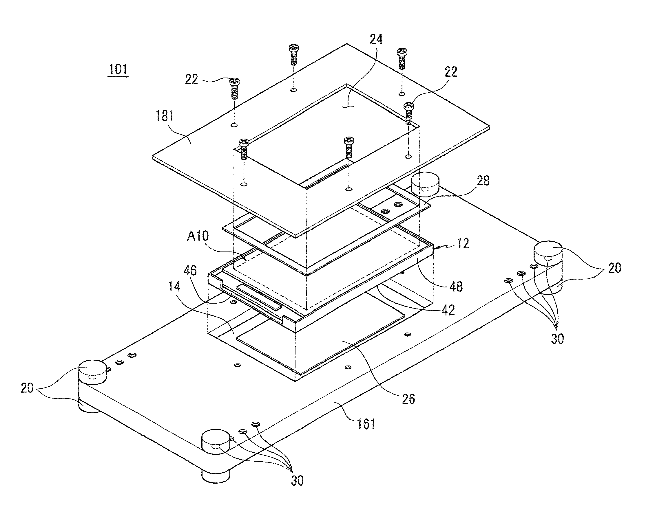
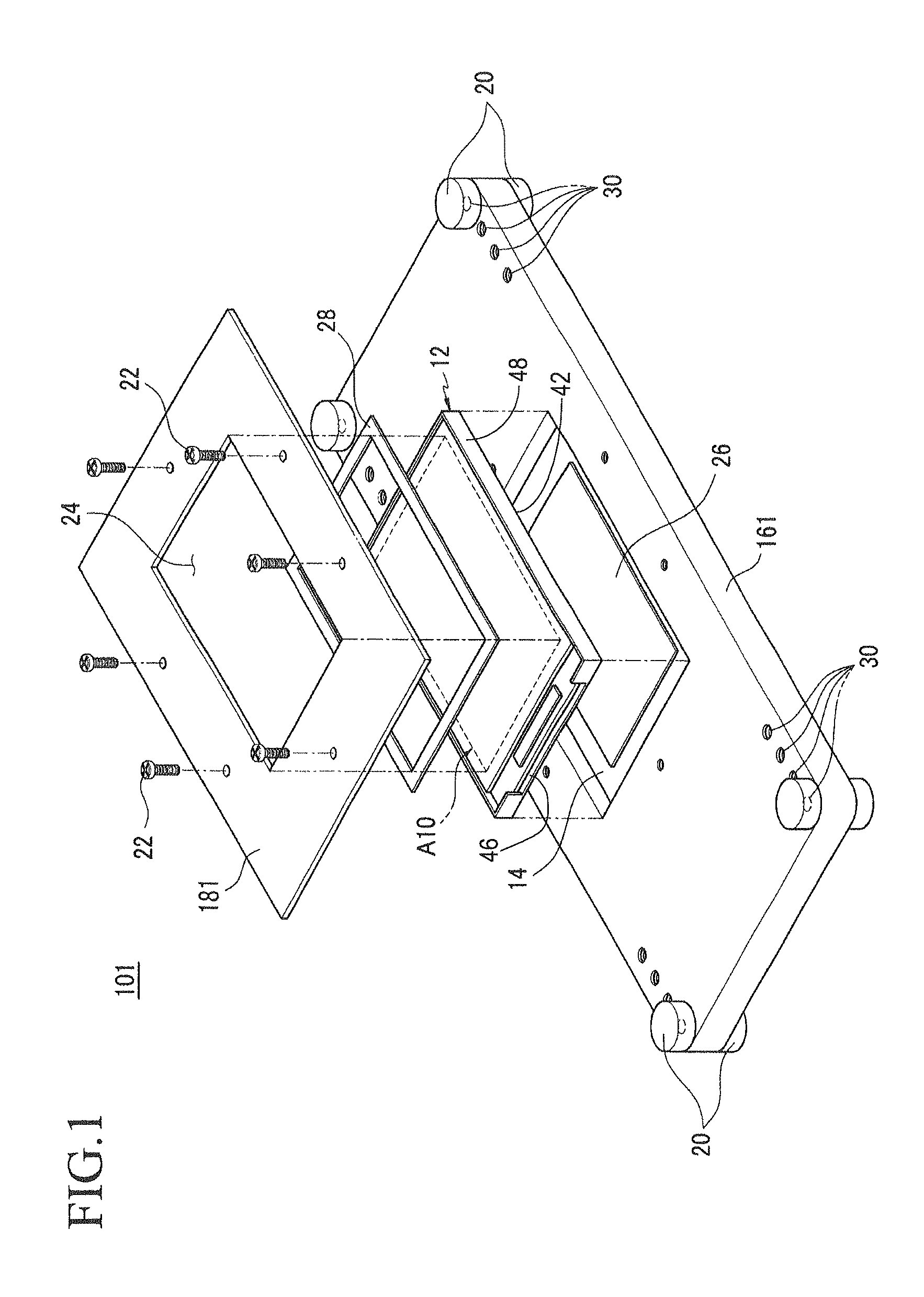
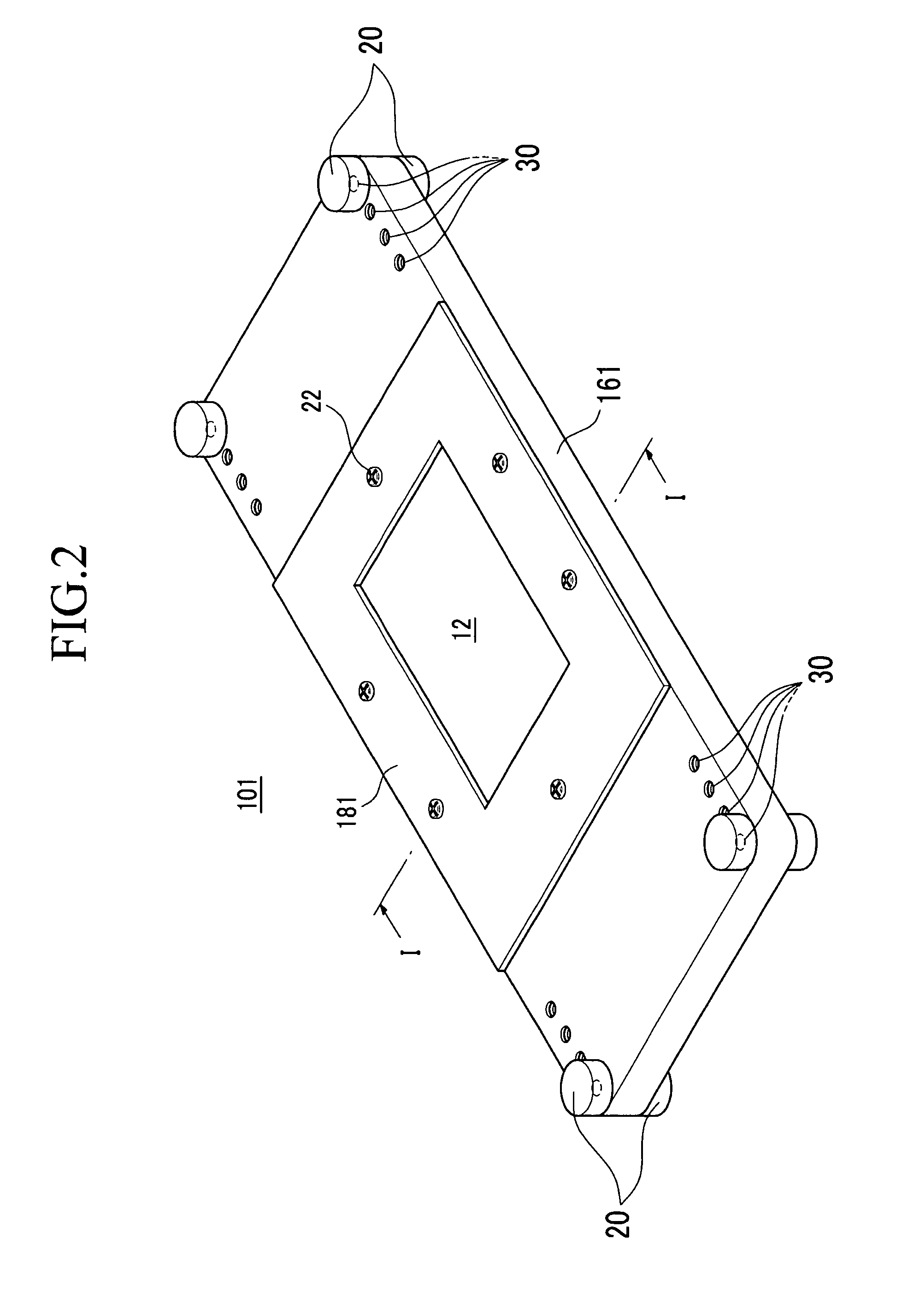
[0042]Referring to FIGS. 1 to 3, a jig frame 101 of the first exemplary embodiment includes a base plate 161 having a groove 14 for receiving a flat panel display 12 and a cover plate 181 overlapping the flat panel display 12 and base plate 161 and fixing the flat panel display 12. The cover plate 181 is coupled to the base plate 161. Balance weights 20 are installed on an edge of the base plate 161.

[0043]The base plate 161 may be formed in a rectangul...


PUM

PropertyMeasurementUnit
thicknessaaaaaaaaaa
thicknessaaaaaaaaaa
weightaaaaaaaaaa

Abstract

A jig frame for a drop test of a flat panel display, which is designed to allow a tester to effectively identify if the flat panel display is damaged and to easily adjust its weight and degree of deformation is provided. The jig frame for a drop test of a flat panel display includes a base plate having a groove for receiving the flat panel display and a cover plate fixing the flat panel display by covering the flat panel display and being coupled to the base plate. The cover plate is formed of transparent material so that the flat panel display installed in the jig frame is visible to outside of the cover plate.

Description

CLAIM OF PRIORITY[0001]This application claims priority to and the benefit of Korean Patent Application Nos. 10-2007-0139027 filed on Dec. 27, 2007 and 10-2008-0002746 filed on Jan. 9, 2008, in the Korean Intellectual Property Office, the entire contents of which are incorporated herein by references.BACKGROUND OF THE INVENTION[0002]1. Field of the Invention[0003]The present invention relates to a jig frame for a drop test of a flat panel display. More particularly, the present invention relates to a jig frame for a drop test of a flat panel display, which is designed to allow a tester to effectively identify if the flat panel display is damaged.[0004]2. Description of the Related Art[0005]In recent years, slim, light-weight flat panel displays have been widely used to overcome disadvantages of cathode ray tubes. Organic light emitting diode (OLED) displays and liquid crystal displays (LCDs) are representative of the flat panel displays and are widely used as displays of mobile elec...

Claims


Application Information

Patent Timeline
Patent Type & Authority Patents(United States)
IPC IPC(8): G01N3/00
CPCG01N3/303G02F1/1309
Inventor YEE, DONG-SUHA, KUEN-DONGHWANG, HYUN-MINMOON, CHAN-KYOUNGLEE, HYUN-HEEIM, JUNG-JUNKWON, OH-JUNEKANG, JI-HO
Owner SAMSUNG DISPLAY CO LTD
Why Eureka
Try Eureka