Imaging method and device employing sherar waves

a shear wave and generator device technology, applied in the direction of instruments, heat measurement, specific gravity measurement, etc., can solve the problems of tedious user, method does not enable the observation of certain zones in viscoelastic medium, and the weight of the generator device is relatively heavy, so as to achieve the effect of reducing the drawbacks

Active Publication Date: 2007-08-07
SUPER SONIC IMAGINE
View PDF16 Cites 113 Cited by
  • Summary
  • Abstract
  • Description
  • Claims
  • Application Information

AI Technical Summary

Benefits of technology

[0016]A particular object of the present

Problems solved by technology

However that known method does not enable certain zones to be observed in the viscoelastic medium, and in particular:
In addition, if the observation field is partially in a shadow zone, it can be

Method used


Image

  • Imaging method and device employing sherar waves
  • Imaging method and device employing sherar waves
  • Imaging method and device employing sherar waves

Examples


Embodiment Construction

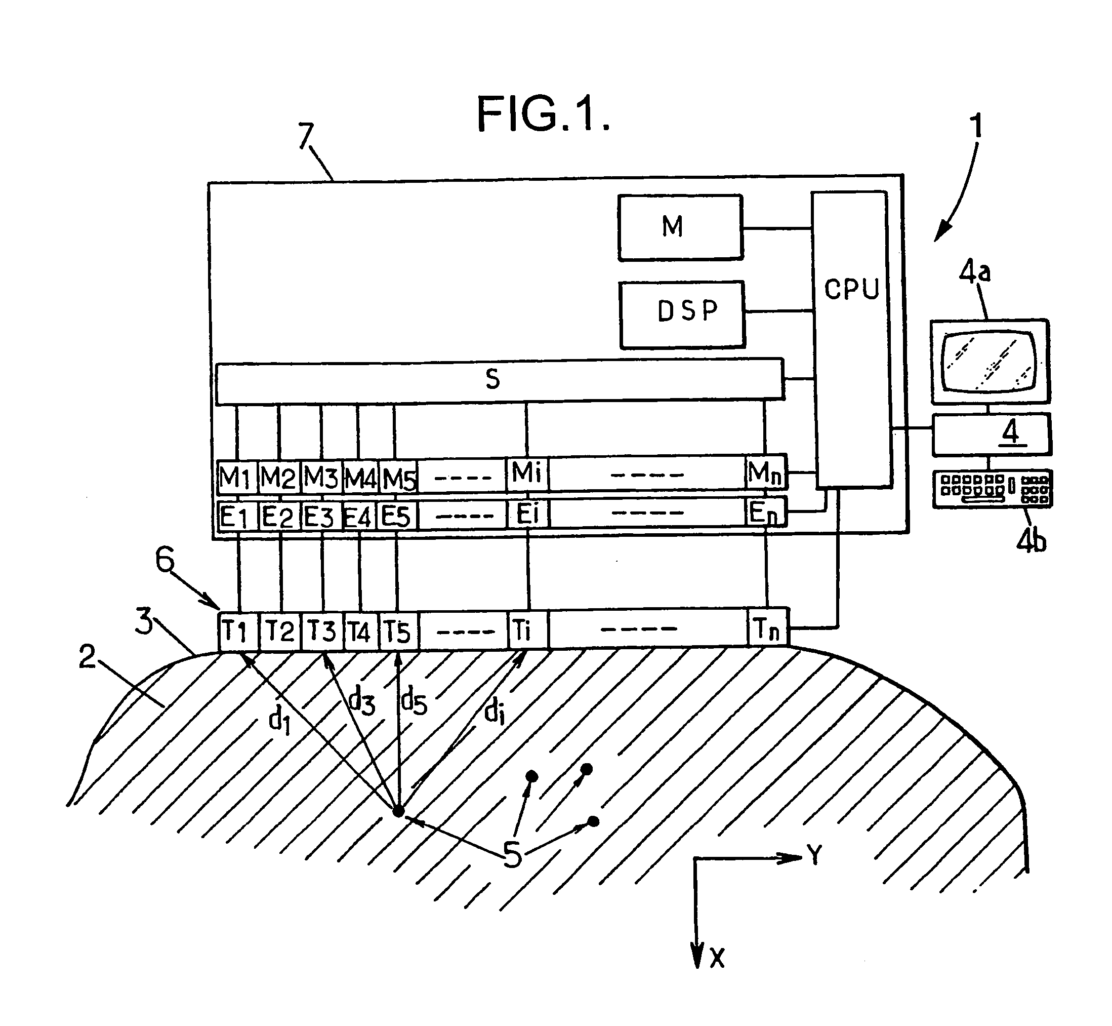
[0044]The imaging device 1 shown in FIG. 1 is for studying the propagation of elastic shear waves in a viscoelastic medium 2 that diffuses ultrasound waves in compression, and that may be constituted, for example:

[0045]by an inert body, in particular for quality control in industrial applications; or

[0046]a living body, for example a portion of the body of a patient, in medical applications.

[0047]By way of example, these movements are tracked by means of a microcomputer 4 (comprising at least an input interface 4a such as a keyboard, etc., and an output interface such as a screen, etc.) or any other electronic central unit, serving to send ultrasound compression waves into the medium 2 from its outside surface 3, which waves interact with diffusing particles 5 contained in the medium 1, which particles are reflective for ultrasound compression waves. The particles 5 may be constituted by any non-uniformity in the medium 1, and in particular, in a medical application, they may be con...


PUM


Abstract

An imaging method for observing the propagation of a shear wave simultaneously at a multitude of points in a diffusing viscoelastic medium. The shear wave is caused to be generated by firing at least one focused ultrasound compression wave into the viscoelastic medium by means of an array of transducers, and then emitting at a fast rate and using the same array of transducers, unfocused ultrasound compression waves serving to obtain a succession of images of the medium, and processing the images obtained in this way in deferred time in order to determine the movements of the medium during the propagation of the shear wave.

Description

FIELD OF THE DISCLOSURE[0001]The present invention relates to imaging methods and apparatuses using shear waves.BACKGROUND OF THE DISCLOSURE[0002]More particularly, the invention relates to an imaging method using shear waves for observing a diffusing viscoelastic medium containing particles that reflect ultrasound compression waves, said method comprising:[0003]a) an excitation step during which an elastic shear wave is generated in the viscoelastic medium;[0004]b) an observation step during which the propagation of the shear wave is observed simultaneously at a multitude of points in an observation field in the viscoelastic medium, this observation step comprising the following substeps:[0005]b1) causing an array of transducers that are controlled independently of one another to emit into the viscoelastic medium a succession of unfocused ultrasound compression wave shots at a rate of at least 500 shots per second; and[0006]b2) causing sound signals received from the viscoelastic m...

Claims


Application Information

Patent Timeline
IPC IPC(8): G01N29/024A61B8/00A61B8/08G01S7/52
CPCA61B8/08A61B8/485G01S7/52026G01S7/52038G01N2291/02827G01S7/52022G01S7/52071G01S15/8915G01S7/52042
Inventor FINK, MATHIAS A.TANTER, MICKAEL
Owner SUPER SONIC IMAGINE
Why Eureka
Try Eureka