Lightning protection device of wind power blade

A lightning protection device and wind power blade technology, which is applied in wind power generation, wind turbines, machines/engines, etc., can solve the problems of unguaranteed thread processing roughness, multiple corners, and easy virtual connections, etc., and achieve excellent contact and connection strength , improve the internal insulation performance, improve the effect of current distribution

Inactive Publication Date: 2021-08-31
苏州风雷盾智能科技有限公司
View PDF9 Cites 4 Cited by
  • Summary
  • Abstract
  • Description
  • Claims
  • Application Information

AI Technical Summary

Problems solved by technology

[0004] Such a setting leads to two types of problems. First, the existing problems of threaded connection: 1. The processing roughness of the thread cannot be guaranteed, the thread contact surface is small, and it is easy to have a virtual connection.
The thread is prone to heat during the lightning guiding process, and the ignition (air breakdown) will cause the thread to be welded to death, and even ignite the surrounding combustibles
2. Irregular thread conduction is accompanied by huge electric force, which may cause the thread to break from the defect
2. Problems in terminal connection: 1. Terminals are used to connect the base and wires. Prone to gap breakdown discharge
2. The base needs to be designed to be connected to the terminal, and also needs to be connected to the lightning receptor, so the volume is large, and the base is generally installed on the trailing edge of the blade. In many cases, the space at this position is limited, and interference is likely to occur during installation
3. The shape of the base is complex, with many corners, which is easy to discharge at the tip and cause lightning

Method used


Image

  • Lightning protection device of wind power blade
  • Lightning protection device of wind power blade
  • Lightning protection device of wind power blade

Examples


Embodiment Construction

[0023] In order to make the purpose, technical solution and advantages of the present invention clearer, the present invention will be further described in detail below through specific implementation methods in conjunction with the accompanying drawings. It should be understood that the specific embodiments described here are only used to explain the present invention, not to limit the present invention.

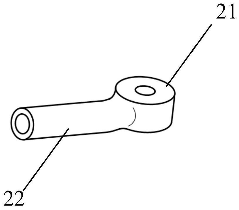
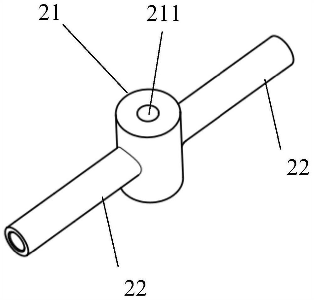
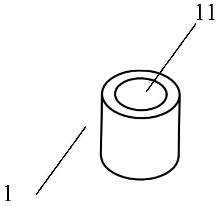
[0024] In one embodiment, such as Figure 1-Figure 6 As shown, a lightning protection device for wind turbine blades is provided, including: lightning receptor 1, base 2 and bolt 3, lightning receptor 1 is a cylinder, one end of which is provided with a counterbore 11; base 2 is composed of a circular tube 22 and Composed of a cylinder 21, the round tube 22 is arranged on the side surface of the cylinder 21 to form a smooth transition; the cylinder 21 is provided with a threaded through hole 211, and one end surface of the cylinder 21 is in contact with one end surface of t...


PUM


Abstract

The invention provides a lightning protection device of a wind power blade. According to the lightning protection device of the wind power blade, a lightning arrester and a base are attached in an end face contact mode, and the sufficient current-carrying sectional area is guaranteed; the lightning arrester and the base are connected through bolts, the bolts apply pressure to the lightning arrester evenly after torque is applied, and it is guaranteed that contact faces have sufficient contact and connection strength; a counter bore is formed in the lightning arrester, so that a current conduction path is increased, current distribution is improved, current-carrying capacity is improved, and temperature rise is reduced; a base cylinder and a circular tube part are in smooth transition, so that current is smoothly conducted, a base circular tube and a wire are connected in a crimping mode, the crimping mode has excellent contact and connection strength, and electric conduction is stable and reliable; and an injection molding material layers are arranged on the outer surfaces of the lightning arrester and the base and extend to the wire to form insulation sealing, so that no metal is exposed in the blade, the internal insulation performance is improved, and leading, lightning triggering and shell breakdown caused by internal metal are avoided.

Description

technical field [0001] The invention relates to the technical field of wind power blades, in particular to a lightning protection device for wind power blades. Background technique [0002] Due to the distribution of wind resources, wind farms are generally located in high mountains or open coastal areas and seas, and wind turbine blades are located at the highest position of wind turbines, so they naturally become the components with the highest probability of being struck by lightning in wind turbines. As the single-unit capacity of my country's onshore wind turbines increases, the height of the hub and the diameter of the impeller continue to increase, making the wind turbines more likely to be struck by lightning during operation. [0003] In order to reduce the risk of being struck by lightning, the lightning protection device is used for lightning protection. The lightning protection of the blade depends on the lightning protection device, which is transmitted to the b...

Claims


Application Information

Patent Timeline
Patent Type & Authority Applications(China)
IPC IPC(8): F03D80/30
CPCF03D80/30Y02E10/72
Inventor 张小燕张鼻祖
Owner 苏州风雷盾智能科技有限公司
Why Eureka
Try Eureka