Switch

a technology of switch and terminal, which is applied in the field of switches, can solve the problems of difficult constitution to ensure sufficient contact pressure against the pair of terminals, deterioration of press operation feeling, and inability to obtain the desired elastic property of the spring for bias in the return direction, etc., and achieves simple constitution, enhanced feeling of press operation of the plunger, and enhanced electrical conductivity between the terminals. reliability

Active Publication Date: 2013-12-05
ORMON CORP
View PDF3 Cites 3 Cited by
  • Summary
  • Abstract
  • Description
  • Claims
  • Application Information

AI Technical Summary

Benefits of technology

[0045]Further, the above-mentioned firm attachment of the terminal contact spring to the plunger can be realized by the attachment of the terminal contact spring to the plunger, and therefore, there is no need to additionally dispose a constitution for fixing the engagement portion under pressure to the plunger so that a simple constitution can be realized by an a...

Problems solved by technology

However, in the case of the constitution, like the “miniature switch” of Japanese Utility Model Publication No. 4-22500, in which the large diameter coil portion and the small diameter coil portion are disposed in series, when the plunger is pressed, a desired elastic property cannot be obtained with respect to the spring for bias in the return direction.
Therefore, there are some problems that it is difficult for the operator, like perceiving the press, and the feeling of press operation is deteriorated.
Accordingly, it should be difficult for the constitution to ensure sufficient contact pressure against the pair o...

Method used


Image

  • Switch
  • Switch
  • Switch

Examples


first embodiment

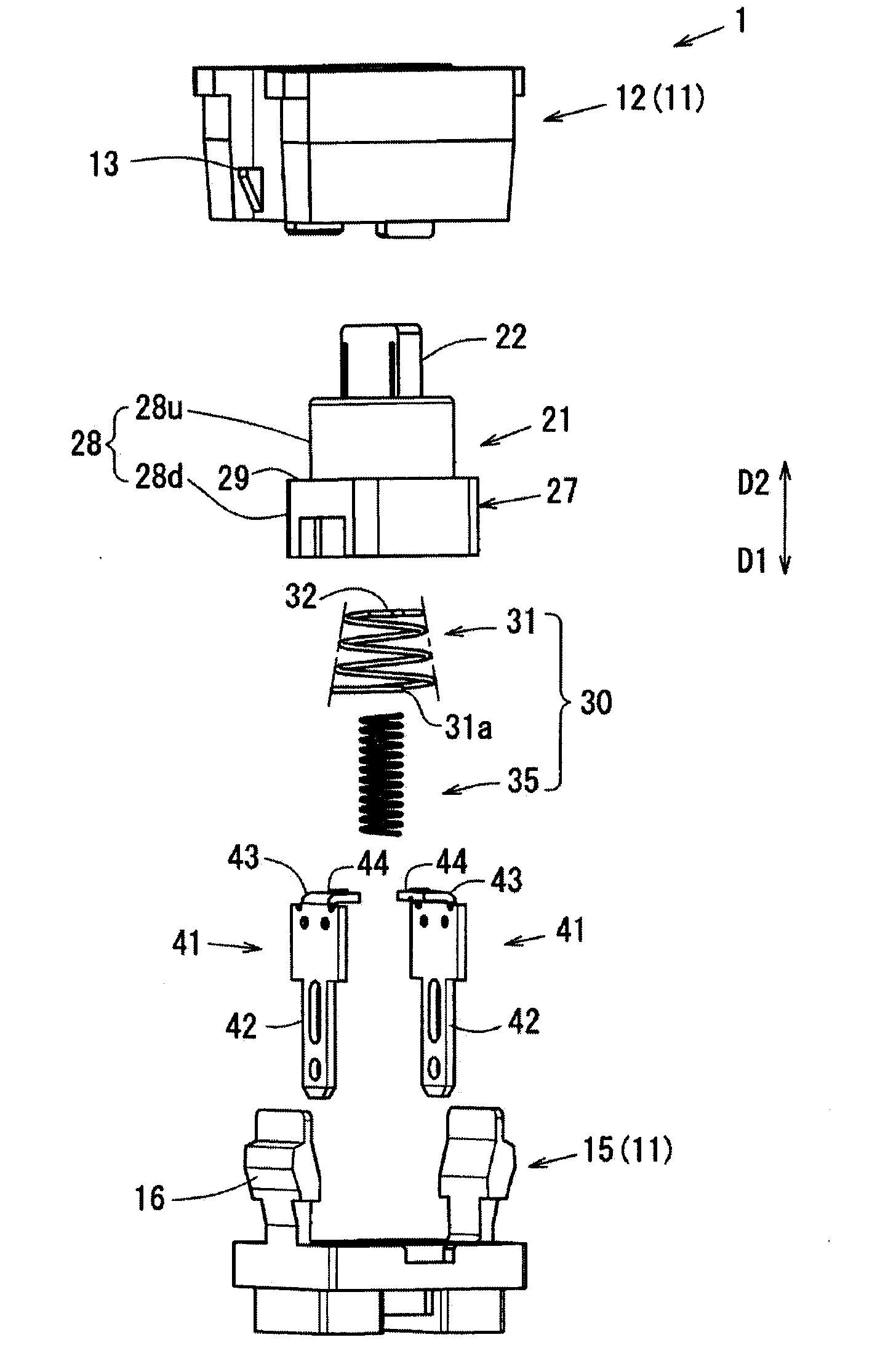
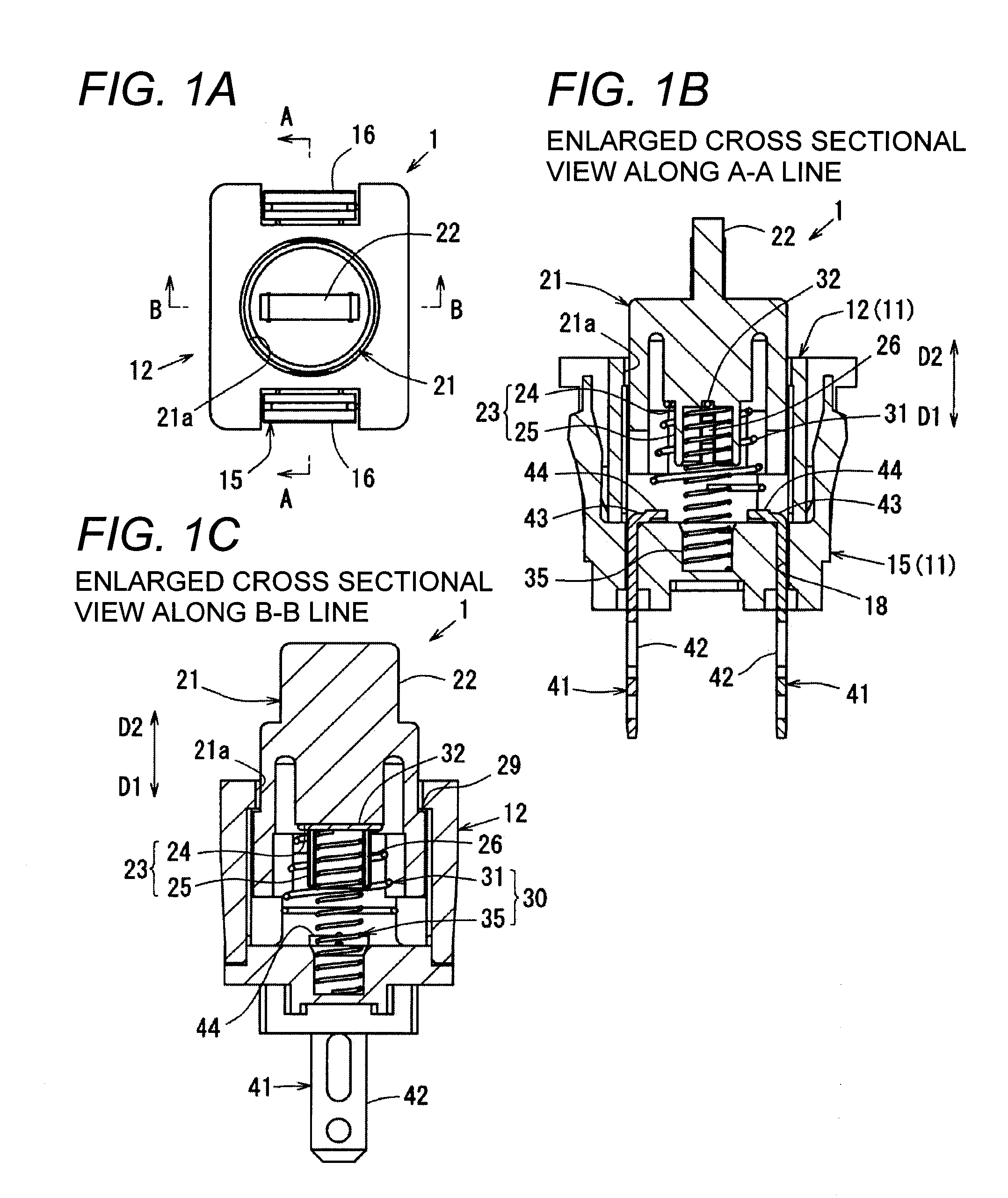
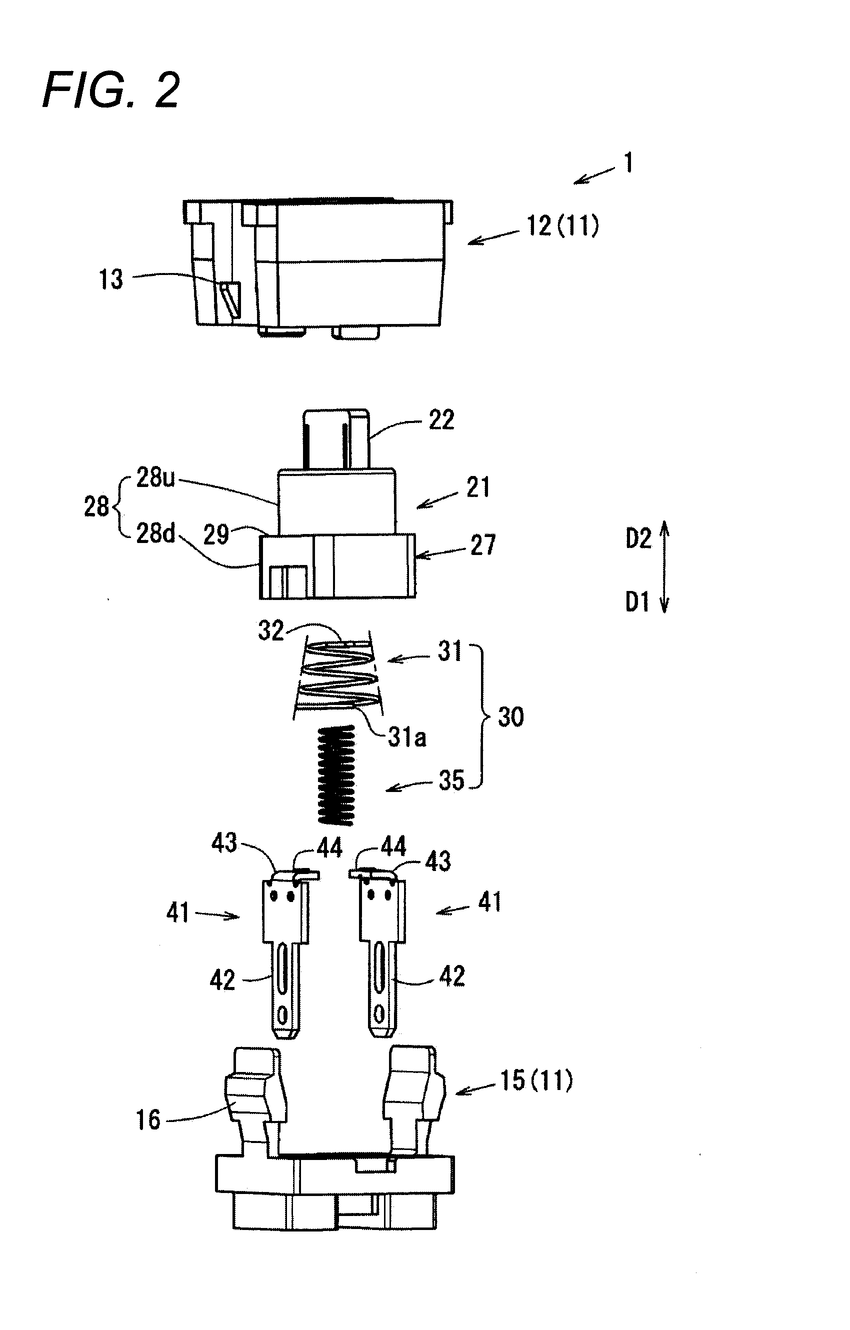
[0060]As illustrated in FIG. 1A to FIG. 3B, a switch 1 is constituted by a housing 11, a plunger 21 which slides in a press direction D1 or a return direction D2 with respect to the housing 11, a spring 30, and a pair of terminals 41 which are brought into a conductive state according to a press of the plunger 21.

[0061]Note that, FIG. 1A is a plan view of the switch 1, FIG. 1B is an enlarged cross sectional view along the A-A line in FIG. 1A, and FIG. 1C is an enlarged cross sectional view along the B-B line in FIG. 1A. FIG. 2 is an exploded perspective view of the switch 1. FIG. 3A is a perspective view, which is seen from the press direction D1 side of the switch 1, of a state in which a terminal contact spring 31 is not mounted to the plunger 21 yet. FIG. 3B is a perspective view, which is seen from the press direction D1 side of the switch 1, of a state in which a return spring 35 is not mounted to the plunger 21 yet.

[0062]Moreover, for convenience, as illustrated in FIGS. 1B a...

second embodiment

[0126]Next, a switch 1A of a second embodiment will be described.

[0127]However, among the constitutional elements of the switch 1A described below, the constitutional elements similar to those of the above-mentioned switch 1 according to the first embodiment will be denoted with the same reference signs, and their explanations will be omitted.

[0128]As illustrated in FIGS. 6A, 6B, and 6C, and FIG. 7, in the switch 1A of the second embodiment, spring compression holding portions 60, which hold the terminal contact spring 31 under a compressed state, are formed at the plunger 21.

[0129]Note that, FIG. 6A is a plan view of the switch 1A, FIG. 6B is an enlarged cross sectional view along the C-C line of FIG. 6A, and FIG. 6C is an enlarged cross sectional view along the D-D line of FIG. 6A. FIG. 7 is an exploded perspective view of the switch 1A.

[0130]As illustrated in FIGS. 6A, 6B, and 6C, and FIG. 7, a pair of spring compression holding portions 60 are formed so as to be opposite to each...


PUM


Abstract

This invention provides a switch including a housing, a plunger that slides in a press direction or a return direction with respect to the housing, a return spring that biases the plunger in the return direction and is compressed by a slide of the plunger in the press direction, a plurality of terminals that are brought into a conductive state according to a predetermined position of the plunger, and a terminal contact spring that makes contact with the terminals so as to bring the terminals into a conductive state by the slide of the plunger in the press direction. The terminal contact spring is disposed so as to be compressed according to the slide of the plunger in the press direction under a contact state of making contact with the terminals.

Description

CROSS REFERENCE TO RELATED APPLICATION[0001]This application claims benefit of priority to Japanese Patent Application No. 2012-116248, filed on May 22, 2012 of which full contents are added by herein.BACKGROUND OF THE INVENTION[0002]This invention relates to a switch which is required to meet specifications having high contact reliability, such as a switch which is built in a controller button of a game machine.[0003]In convention, as a switch of a type whose contacts are brought into a conductive state by pressing a plunger, for example, various switches have been developed for obtaining sufficient contact pressure at the contacts, and excellent feeling of press operation of the plunger.[0004]For example, one of them is disclosed in Japanese Utility Model Publication No. 4-22500 as a “miniature switch”.[0005]The “miniature switch” of Japanese Utility Model Publication No. 4-22500 is constituted by a housing which is configured by a switch base, and a switch cover fitted into the s...

Claims


Application Information

Patent Timeline
IPC IPC(8): H01H1/20
CPCH01H1/20H01H1/242H01H13/52H01H13/12
Inventor TANIGUCHI, AKIOKIYONO, YASUHIRO
Owner ORMON CORP
Why Eureka
Try Eureka