Method and device for fixing and correcting spondylolisthesis anteriorly

Inactive Publication Date: 2000-05-02
SPINEOLOGY
View PDF3 Cites 426 Cited by
  • Summary
  • Abstract
  • Description
  • Claims
  • Application Information

AI Technical Summary

Problems solved by technology

That patent has a disadvantage in requiring removal of the disk and having multiple steps, that is, two implants are inserted into the disk space only to be su

Method used


Image

  • Method and device for fixing and correcting spondylolisthesis anteriorly
  • Method and device for fixing and correcting spondylolisthesis anteriorly
  • Method and device for fixing and correcting spondylolisthesis anteriorly

Examples


Embodiment Construction

is hereafter described with specific reference being made to the drawings in which:

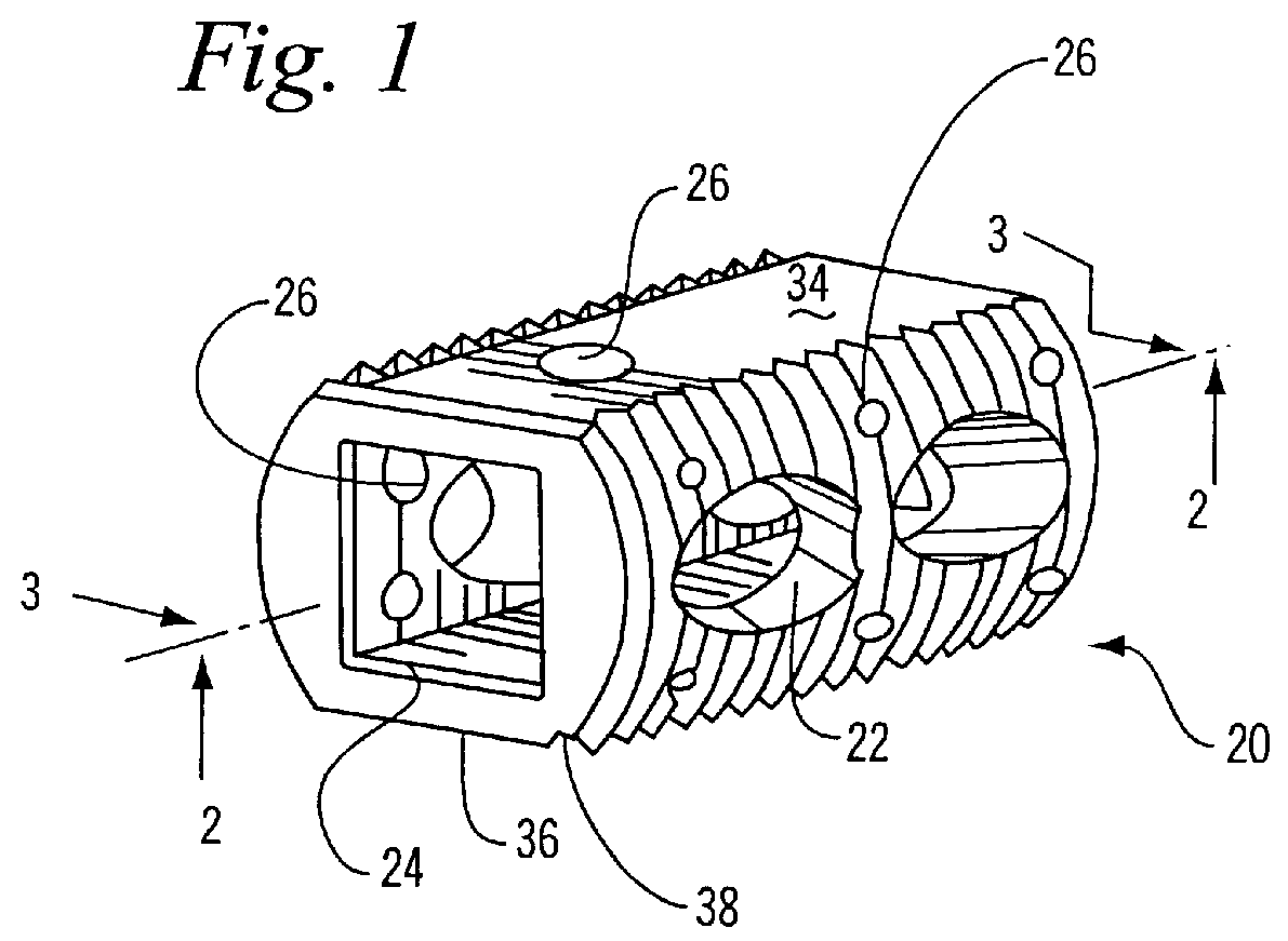
FIG. 1 is a perspective view of the disk cage of the invention;

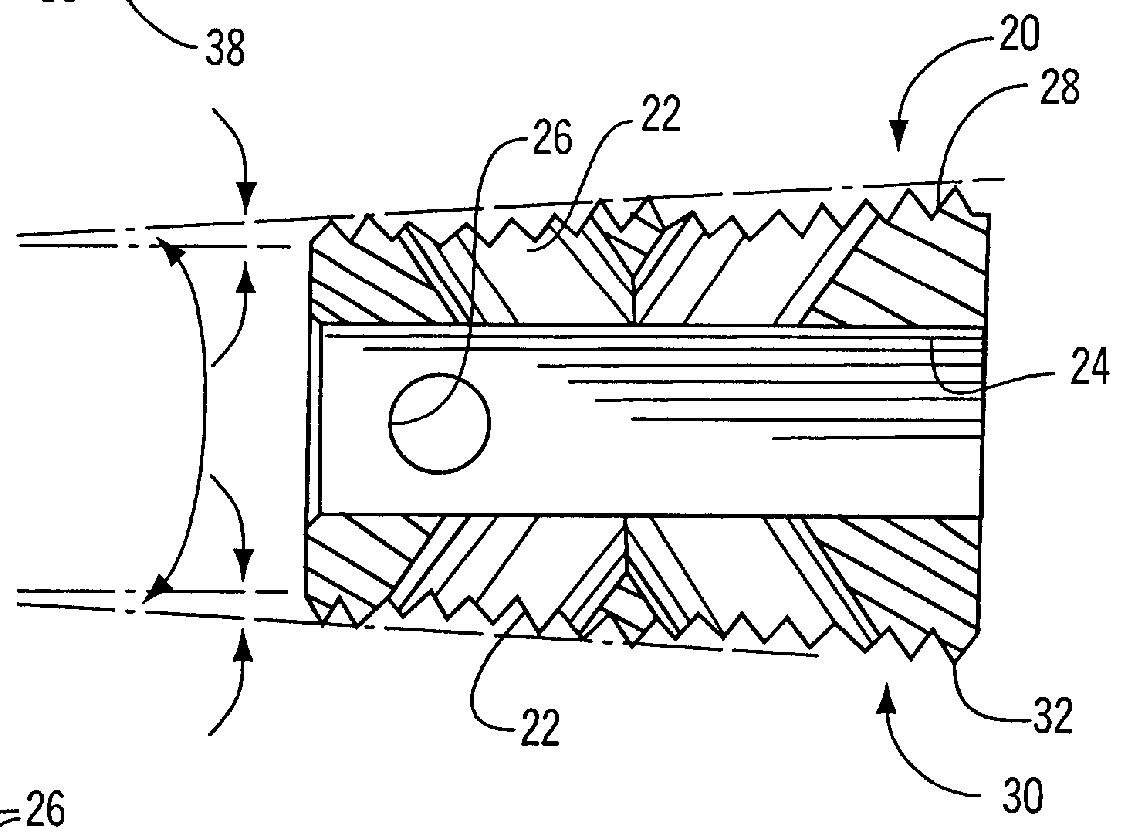
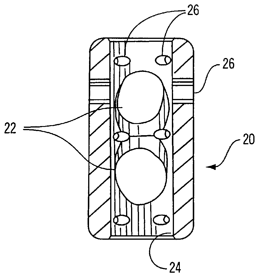
FIG. 2 is a cross-sectional view of the disk cage through line 2--2 of FIG. 1;

FIG. 3 is a cross-sectional view of the disk cage through line 3--3 of FIG. 1;

FIG. 4 is an enlarged partial view of a corner of the cage of the invention;

FIG. 5 is a perspective view of the end of an insertion device for the disk cage;

FIG. 6 is a cross-sectional view of the insertion device of FIG. 5 inserted into a disk cage;

FIG. 7 is a perspective view of the screw alignment device of the invention;

FIG. 8 is a perspective view of a distracting tool for aligning adjacent vertebrae;

FIG. 9 shows the distracting tool being used to lift and distract one vertebra from an adjacent vertebra;

FIG. 10 shows the vertebrae properly aligned from FIG. 9 and reaming of the disk space;

FIG. 11 shows a threaded, hollow, screw for use in securing adjacent vertebrae together throug...


PUM


Abstract

A method and apparatus for fixation and correction of spondylolisthesis anteriorly includes a disk cage which is inserted into the space between adjacent vertebrae, a drill guide for guiding and aligning a drill bit to angle an opening anteriorly between adjacent vertebrae, a distractor for temporarily aligning the vertebrae to position a disk cage and an elongated hollow screw positioned in said drilled opening through one vertebra, said disk cage and into said adjacent vertebra.

Description

1. Field of the InventionThis invention relates to a method and apparatus for fixation and reduction of spondylolisthesis, e.g., misalignment of the vertebrae comprising the spinal column. More specifically, the present invention relates to a disk cage positioned in the disk space between affected vertebra, and a screw through said vertebra, disk cage and other vertebra and a method utilizing that apparatus.2. Description of the Related ArtTreatments for conditions involving subluxation of one vertebrae upon another, resulting in misalignment of the spinal column, involve the use of screws which extend through a plate and which are tightened to draw the misaligned vertebrae back into alignment. U.S. Pat. No. 5,531,747 to Ray (hereinafter "Ray") is an example of a plate and screw system for treating spondylolisthesis. Other approaches include insertion of an implant into the disk space between misaligned vertebrae such as shown in U.S. Pat. No. 5,601,556 to Pisharodi (hereinafter "Pi...

Claims


Application Information

Patent Timeline
IPC IPC(8): A61B17/16A61B17/17A61B17/68A61B17/86A61F2/44A61F2/46A61B17/02A61F2/28A61F2/30
CPCA61B17/025A61B17/1757A61B17/864A61F2/447A61F2/4611A61B2017/0256A61F2/442A61F2002/4627A61F2002/2835A61F2002/30777A61F2002/30785A61F2002/30789A61F2002/30858A61F2002/4475A61F2002/30593
Inventor KUSLICH, STEPHEN D.
Owner SPINEOLOGY
Why Eureka
Try Eureka