Continuous cell mattress overlay with flowable filler material of buckwheat hulls

a continuous cell, mattress technology, applied in the field of mattress overlays, can solve the problems of not employing a continuous cell construction that is cheap, not easily adaptable to existing beds, and not designed for mass marketing and general public sleeping comfort,

Inactive Publication Date: 2000-05-09
HENRY LLOYD W
View PDF13 Cites 32 Cited by
  • Summary
  • Abstract
  • Description
  • Claims
  • Application Information

AI Technical Summary

Problems solved by technology

These pillow mattresses included a longitudinal support for the mattress, making them both bulky and not easily adaptable for use on existing beds.
They do not employ continuous cell construction that is cheap and easily manufactured.
These are full sized, fixed mattresses filled with materials that do not allow for natural air circulation.
These pillow mattresses are not designed for mass marketing and the sleeping comfort of the general public.
This pillow is for comfort and support of the cervical area of the neck and head and is unsuitable in size and design for use as a mattress overlay.
Again, the overlay's stated use is to give comfort to bedsore sufferers and is not suitable for general use by the public.
The above overlay and mattresses lack portability for those traveling or temporarily relocated.
At this angle the GERD sufferer's slippage, as well as that of a double bed sleeping partner, is a problem as the friction between overlay and mattress and human body and overlay is not sufficient to stop slippage as body movement occurs.
The solution using foam, as detailed above, creates hot areas for the sleeper where contact is made; the wedges do not allow comfortable sleeping on the side or stomach, the preferred sleep position of the majority of the public.

Method used


Image

  • Continuous cell mattress overlay with flowable filler material of buckwheat hulls
  • Continuous cell mattress overlay with flowable filler material of buckwheat hulls
  • Continuous cell mattress overlay with flowable filler material of buckwheat hulls

Examples


Embodiment Construction

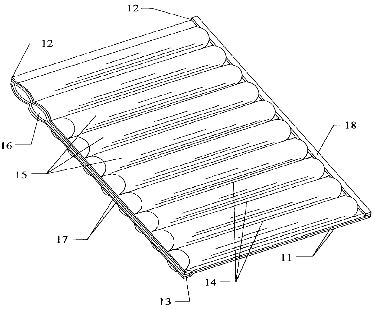
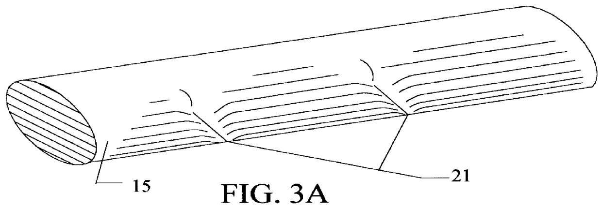
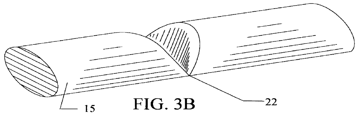
The preferred embodiment of the present invention is illustrated in FIG. 1. It consists of two pieces of fabric 11 joined along one longitudinal (head to foot) edge 12. The opposite longitudinal edge 12 is joined with hook and loop pressure strips 13 (FIG. 2C) that are attached by thread 20 (FIG. 2B). The two pieces of fabric are then joined transversely in direct contact with each other, from side to side 14 on the remaining edges and at predetermined intervals along the longitudinal axis of the fabric, using thread 20. The resulting transverse interior spaces between the transverse joinings create continuous cells 15 between the two pieces of joined fabric. The open cells 16 are then partially filled with Buckwheat hulls. The cells are then closed 17 by applying pressure to the hook and loop pressure strips 13.

The preferred embodiment includes half of a pressure strip 18 (hook or loop) as shown along one of the joined longitudinal edges 12. In the preferred embodiment, attachment ...


PUM


Abstract

A mattress overlay consisting of two pieces of fabric joined along the longitudinal, or head to foot, edges and then joined transversely, from side to side, at predetermined distances along the longitudinal axis forming lateral, closed interior cell spaces. In the preferred embodiment, the joining method along at least one of the longitudinal edges uses openable and recloseable cooperating hook and loop pressure strips to allow access to the individual cells after manufacture. To provide even support throughout the resting area, the interior cell spaces are partially filled with a flowable filler material of Buckwheat hulls or a mixture of Buckwheat hulls and any other compatible material. The preferred embodiment allows resting comfort to be customized by adding or removing flowable filler from individual cell spaces as needed. The preferred embodiment has half of an openable and recloseable fastening device joined along longitudinal edge to allow attachment of two or more mattress overlays. The mattress overlay, when Buckwheat hulls are used as a filler material, resists the slippage of the human resting form when a bed is canted for medical purposes.

Description

BACKGROUND--FIELD OF INVENTIONThis invention relates to mattress overlays, specifically to a mattress overlay with a more general application for providing even support over the entire resting human form.BACKGROUND--DESCRIPTION OF PRIOR ARTThroughout history, human beings have sought a comfortable resting surface. Inventors have created many variations on the straw and feather mattresses of earliest times. Primary surfaces, mattresses, and secondary surfaces, overlays and pads, have evolved from natural products to man made foams and polyurethane. Medical problems, such as bedsores, have been addressed. Thereafter, inventors created resting devices such as cell mattresses, Buckwheat pillows, and polyurethane overlays, to solve specific resting problems for a selected part of the population.Cell mattresses were originated primarily for the relief of bedsores for patients confined for long periods in bed--for example, U.S. Pat. No. 4,163,297 to Neumark (1979) and U.S. Pat. No. 4,843,6...

Claims


Application Information

Patent Timeline
Patent Type & Authority Patents(United States)
IPC IPC(8): A47C27/12
CPCA47C27/12
Inventor HENRY, LLOYD W.
Owner HENRY LLOYD W
Why Eureka
Try Eureka