Directional heat exchanger

a heat exchanger and directional technology, applied in the field of heat exchangers, can solve the problems of difficult cooling of electronic components embodied in the periscope, and the inability to adequately dissipate higher thermal loads within the radom

Inactive Publication Date: 2000-05-09
NAVY US SECA OF THE
View PDF13 Cites 8 Cited by
  • Summary
  • Abstract
  • Description
  • Claims
  • Application Information

AI Technical Summary

Problems solved by technology

Accordingly, providing cooling for electronic components embodied in the periscope is difficult.
However, as operating speeds and capabilities of electronics components increase, the resulting higher thermal loads cannot be adequately dissipated within the radome.

Method used


Image

  • Directional heat exchanger
  • Directional heat exchanger
  • Directional heat exchanger

Examples


Embodiment Construction

)

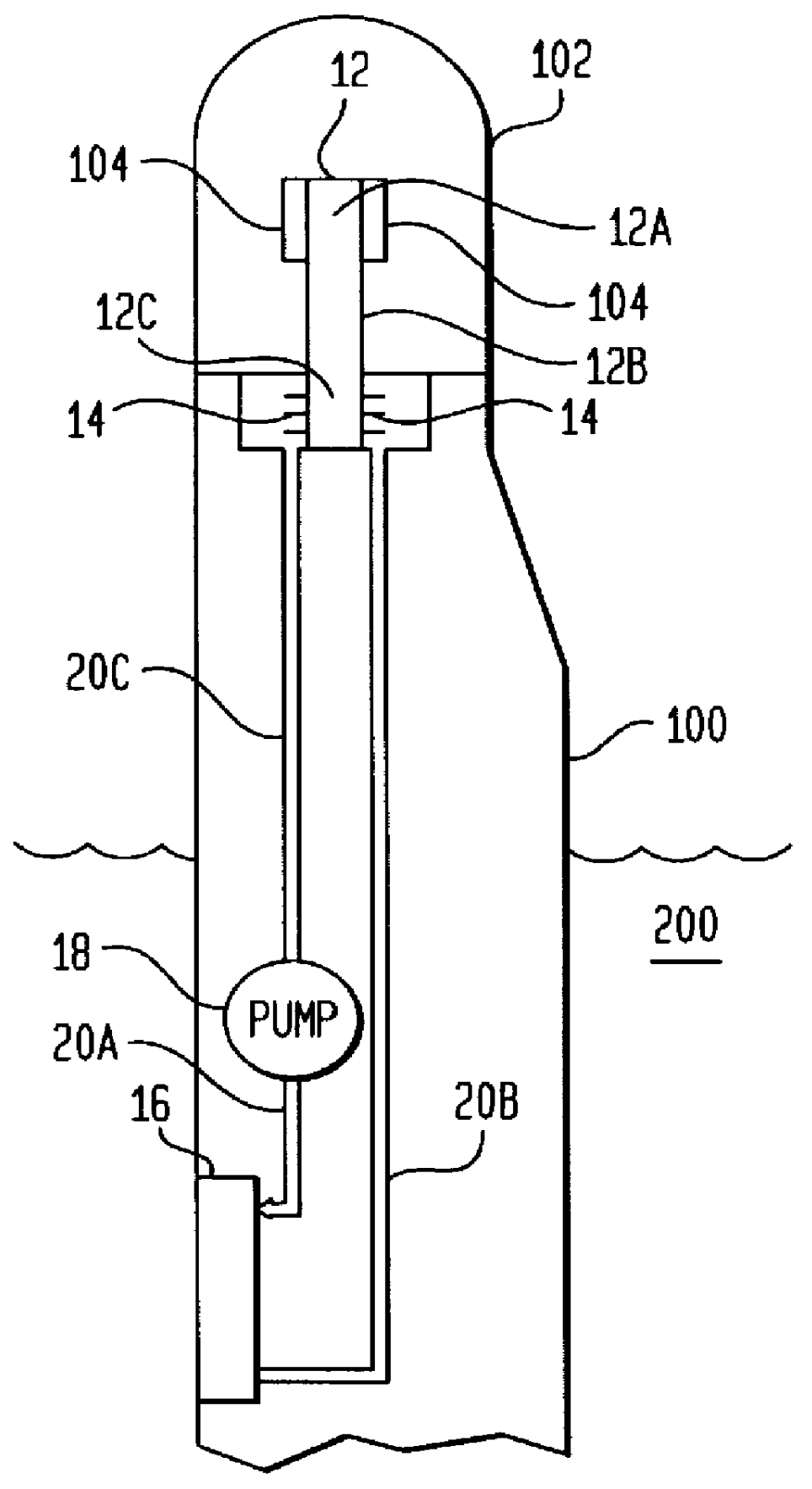
Referring now to the drawings, and more particularly to FIG. 1, a heat exchanger and system of the present invention is shown schematically as it would be installed in a periscope tube 100 (shown in portion) having a thermally insulated antenna radome 102 mounted on top of periscope tube 100. The periscope tube 100 is filled with nitrogen or other gases and is substantially immersed in seawater 200. While the present invention is shown and will be described relative to its use with periscope tube 100 and antenna radome 102, it is to be understood that the present invention can be used with other structures in which heat transfer is preferably directed to a large, thermally-conductive heat sink, e.g., seawater.

The system of the present invention includes a heat pipe 12 that resides partially in radome 102 and partially in periscope tube 100. Antenna components 104 that generate heat to be dissipated are coupled for good heat transfer to heat pipe 12 in any one of a variety of ways k...


PUM


Abstract

A directional heat exchanger system dissipates heat generated by components contained within a thermally insulated antenna mounted atop a periscope tube. A first wall of thermally conductive material has a first face and a second face with the first face being shaped to substantially contact an internal portion of the periscope tube. A plurality of ribs made from thermally conductive material are fixedly coupled to the second face. A second wall of thermally conductive material opposes the second face of the first wall and is in tangential contact with the ribs to form a fluid seal therewith. At least one channel is formed between the first and second walls. The end of each rib is offset from the end of adjacent ribs such that the channel defines a flow path having a first end and a second end. The components generating heat are thermally coupled to a heat pipe positioned partially in the antenna and partially in the periscope tube. A liquid coolant delivery system is coupled to the first and second ends of the flow path to pump a liquid coolant into the first end and recapture the liquid coolant exiting the second end.

Description

(1) Field of the InventionThe present invention relates generally to heat exchangers, and more particularly to a heat exchanger and system constructed to provide a specific direction of heat transfer in order to couple the heat to a preferred heat-dissipating medium.(2) Description of the Prior ArtPeriscopes are one means a submerged submarine uses for communication above the surface. A periscope is designed to reach above the surface while the submarine stays submerged. Many instruments can be embodied in the extreme end of the periscope for communication above the surface. These include the traditional optical periscope, electronic cameras, radio frequency antennas, and laser ranging equipment. Space is limited inside the periscope by the need for extending it above the surface. Accordingly, providing cooling for electronic components embodied in the periscope is difficult.The electronic components of certain periscope antennas are mounted within a thermally insulated environment,...

Claims


Application Information

Patent Timeline
Patent Type & Authority Patents(United States)
IPC IPC(8): B63G8/38B63G8/00F28D15/02F28D1/02F28D1/03
CPCB63G8/38F28F3/12F28D15/02
Inventor SAYEGH, RIAD
Owner NAVY US SECA OF THE
Why Eureka
Try Eureka